Smart sensor network for power grid health monitoring

a smart sensor network and power grid technology, applied in the field of monitoring, can solve the problems of affecting the health of the power grid, posing a tremendous threat or hazard to the personal safety of such individuals, and affecting the security of personal property,

Active Publication Date: 2017-02-23
THE UNIVERSITY OF AKRON
View PDF2 Cites 34 Cited by
  • Summary
  • Abstract
  • Description
  • Claims
  • Application Information

AI Technical Summary

Benefits of technology

[0014]In light of the foregoing, it is a first aspect of the present invention to provide a power transmission line monitoring system comprising a first sensor magnetically coupled to the power transmission line, and configured to inject a high frequency signal therein via the magnetic coupling; a second sensor magnetically coupled to the power transmission line at a predetermined distance from one end of the first sensor, wherein the second sensor blocks the injected signal back toward the first sensor; and a third sensor magnetically coupled to the power transmission line at a predetermined distance from another end of the first sensor, wherein the third sensor blocks the injected signal back toward the first sensor; wherein the first sensor detects the blocked signals from the second and third sensors to determine an impedance of a segment of the power transmission line that is between the second and third sensors.
[0015]It is another aspect of the present invention to provide a method of monitoring a power transmission line comprising the steps of magnetically coupling a first sensor, a second sensor, and a third sensor to the power transmission line, such that the first sensor is positioned between the second sensor and the third sensor at a predetermined distance; injecting a high frequency signal from the first sensor into the power transmission line; blocking the high frequency signal at the second and third sensors back toward the first sensor; and determining at the first sensor an impedance of a segment of the power transmission line that is between the second and third sensors.

Problems solved by technology

Due to their nature, power transmission lines are susceptible to contact faults, which are the result of an unwanted conduction path that has formed between a conductive surface of the power line and a non-conductive surface, such as a tree.
That is, such contact faults are the result of the growth of trees under such power transmission lines, a break in an electrical conductor of the power transmission line, as well as, animal or human contact with the power transmission line.
One type of fault that can impact the power grid is a high-impedance fault.
Since high-impedance faults often result in an energized conductor that is in reach of individuals in the public, it poses a tremendous threat or hazard to both the personal safety of such individuals, and to the security of personal property.
Such a high impedance fault is difficult to detect because the high impedance fault current appears very similar in magnitude to the small variations of the power network load that are experienced in an energized power grid.
While low impedance power line faults can be detected based on the high amount of electrical current passing through the power transmission lines while the power grid / transmission line is energized, the recognition of a fault in a de-energized power grid / transmission line is challenging due to the absence of any electrical current passing through the power transmission line.
However, these techniques suffer from various drawbacks, some of which are discussed below.
Their presence in a power distribution fault causes identification problems.
However, the TDR method is complex, and requires complex hardware.
As such, complex hardware is needed to execute this method.
Thus, such FBG based approaches, again suffer from needing complex hardware.
While this method is useful for detecting the high fault current that is produced by a faulty power line, it is not able to be used to predict the possibility of a fault occurrence in the overhead power line based on the power line's health condition.
Using this method to measure sag in the power line is costly.
However, existing high-frequency impedance measurement devices cannot be directly connected to the energized power grid or network, nor are they capable of measuring the impedance of a specific power transmission line segment.

Method used


Image

  • Smart sensor network for power grid health monitoring
  • Smart sensor network for power grid health monitoring
  • Smart sensor network for power grid health monitoring

Examples


Embodiment Construction

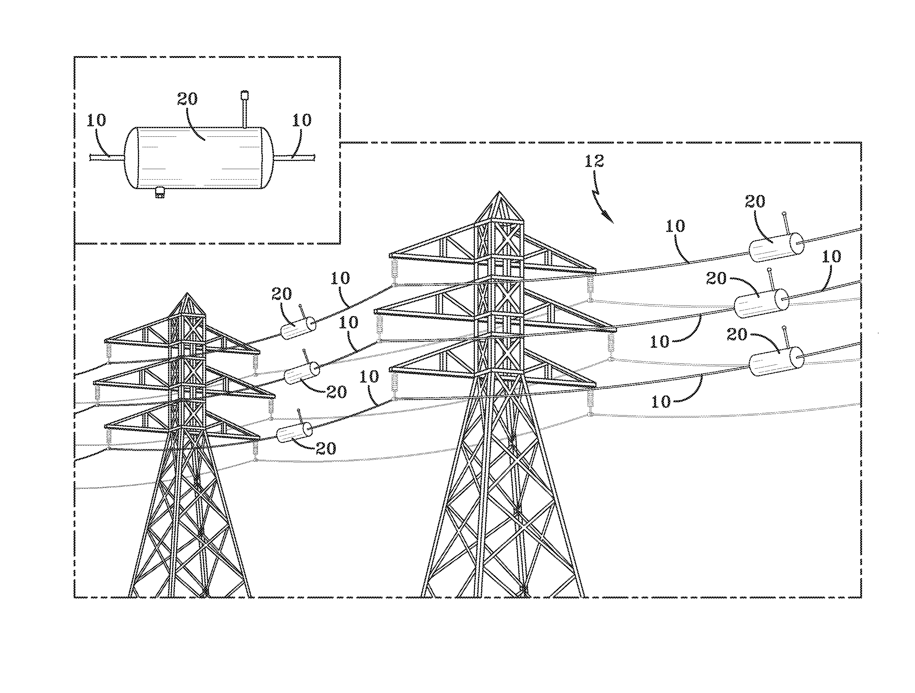
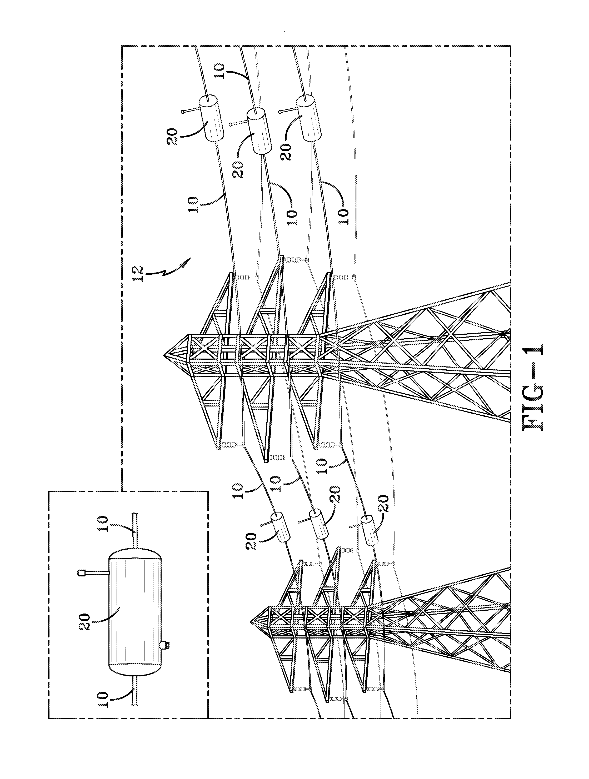
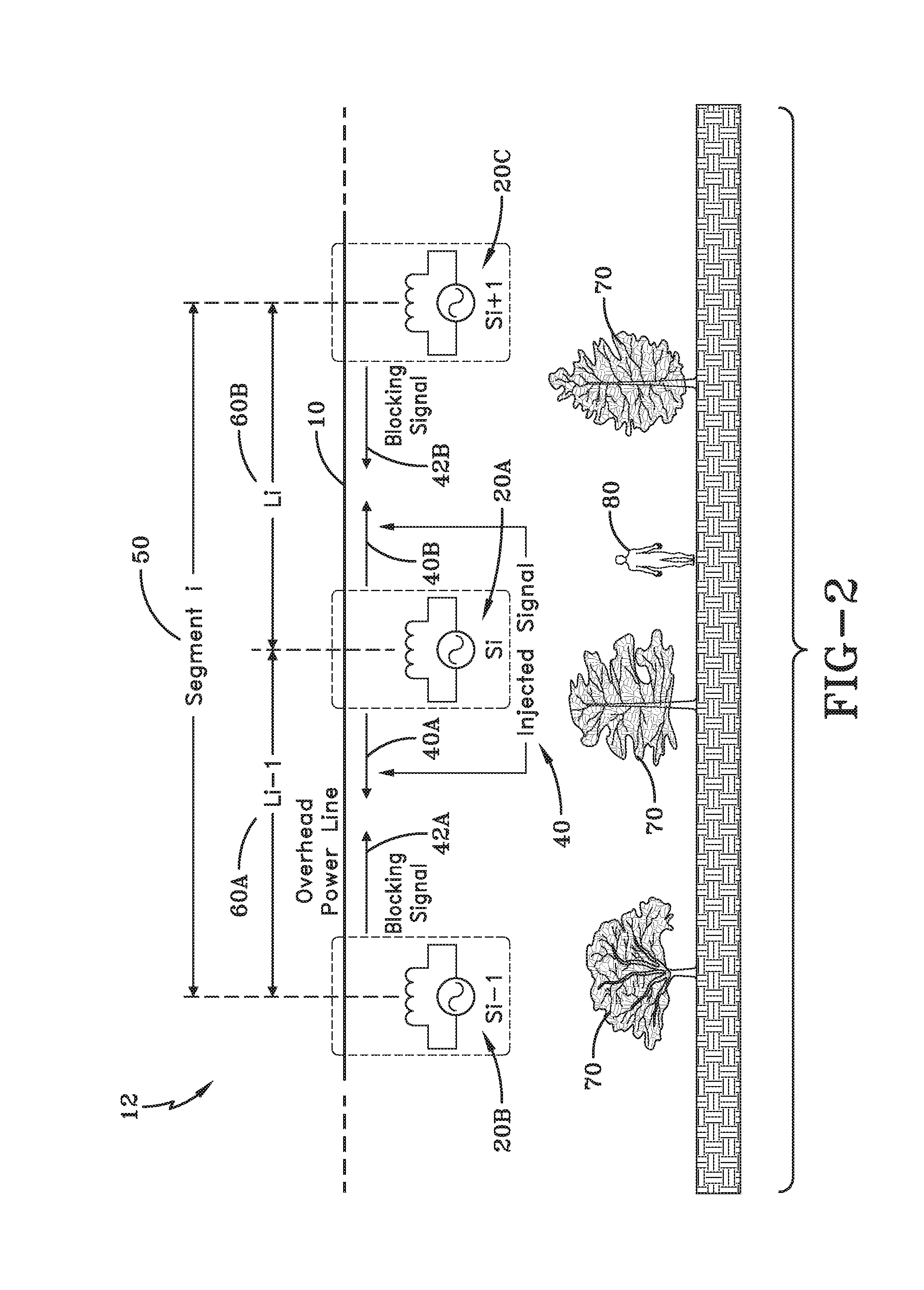
[0022]A smart sensor utilized to monitor the presence of electrical faults in one or more power transmission lines 10 of an electrical power grid 12 is generally referred to by numeral 20, as shown in FIG. 1. The present invention utilizes a plurality of smart sensors 20 to form a smart network to monitor the health condition of the power grid 12 or a portion thereof. Specifically, the smart network, which is formed of a plurality of sensors 20 is also able to detect any type of electrical fault, such as a tree, human or animal contact, or other fault that is due to the poor health condition of the isolators, conductors, or towers, associated with one or more of the power transmission lines 10 of the power grid 12, in real-time. The sensors 20 are also configured to monitor and track the high-frequency impedance change in specific sections or segments of one or more power transmission lines 10 of the power grid 12 being monitored. Thus, because the variation in impedance of the powe...


PUM


Abstract

A smart sensor network for power grid health monitoring includes a plurality of spaced sensors that are magnetically coupled to the power transmission line to be monitored. The sensors include a signal injection unit and a signal sensing unit. As such, one of the sensors acts to inject, via its signal injection unit, a high frequency signal through the magnetic coupling into the power transmission line, while sensors on either side of the signal injecting sensor act to block the injected signal, which is then detected by the signal sensing unit of the injecting sensor, and is used to measure the impedance of the power transmission line segment being analyzed. Based on the difference between a pre-measured impedance of the power transmission line being monitored and the actual impedance value of the power transmission line being measured by the sensor, the health of the power line can be obtained.

Description

CROSS-REFERENCE TO RELATED APPLICATION[0001]This application claims the benefit of U.S. Provisional Application No. 61 / 985,552 filed Apr. 29, 2014, the contents of which are incorporated herein by reference.TECHNICAL FIELD[0002]Generally, the present invention relates to monitoring an electrical power grid formed of power transmission lines. Particularly, the present invention relates to a power grid protection system for detecting high-impedance faults (HIF) that occur on power transmission lines. More particularly, the present invention relates to a power grid protection system that uses a smart sensor network to monitor the health of power transmission lines of an electrical power grid and to detect electrical faults therein in real-time.BACKGROUND OF THE INVENTION[0003]Power transmission lines, which carry electrical power from a power generation plant, are one of the most critical components of an energy generation and transmission system that together forms a power grid. Due t...

Claims


Application Information

Patent Timeline
Patent Type & Authority Applications(United States)
IPC IPC(8): G01R31/02H01H47/00G01R31/58
CPCG01R31/021H01H47/00G01R31/024G01R31/085G01R31/58H02H1/003G01R31/11G01R27/16H02H7/26
Inventor PASDAR, AMIR MEHDISOZER, YILMAZDE ABREU-GARCIA, JOSE ALEXIS
Owner THE UNIVERSITY OF AKRON
Why Eureka
Try Eureka