
Flippable electrical connector

a plug-in connector and flip-in technology, applied in the direction of coupling device connection, electrical apparatus, two-part coupling device, etc., can solve the problem of super-speed signal addition degredation

Active Publication Date: 2017-02-23
FOXCONN INTERCONNECT TECHNOLOGY LIMITED
View PDF4 Cites 29 Cited by
  • Summary
  • Abstract
  • Description
  • Claims
  • Application Information

AI Technical Summary

Benefits of technology

The present invention provides a receptacle connector that can mate with a plug connector. It includes an insulative housing with a widen and thicken step structure near the base, two rows of plate contacts with contacting sections exposed on the mating tongue, and a metallic shielding plate that occupies most of the mating tongue. The shielding plate has immoveable and un-deflectable lateral edge sections in front of the step structure that can be locked with a latch of the plug connector in a transverse direction.

Problems solved by technology

This can be costly and also cause some additional degredation in the super speed signals.

Method used


Image

  • Flippable electrical connector
  • Flippable electrical connector
  • Flippable electrical connector

Examples


first embodiment

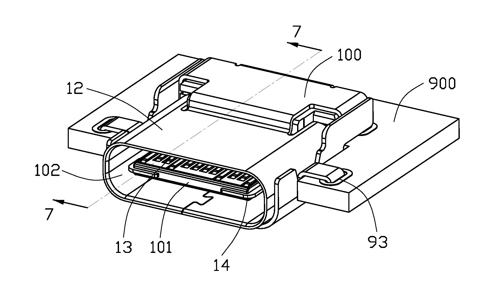
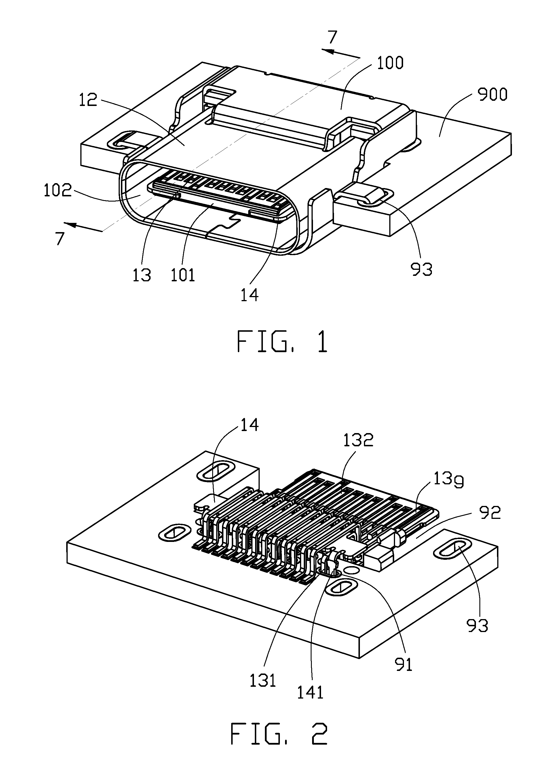
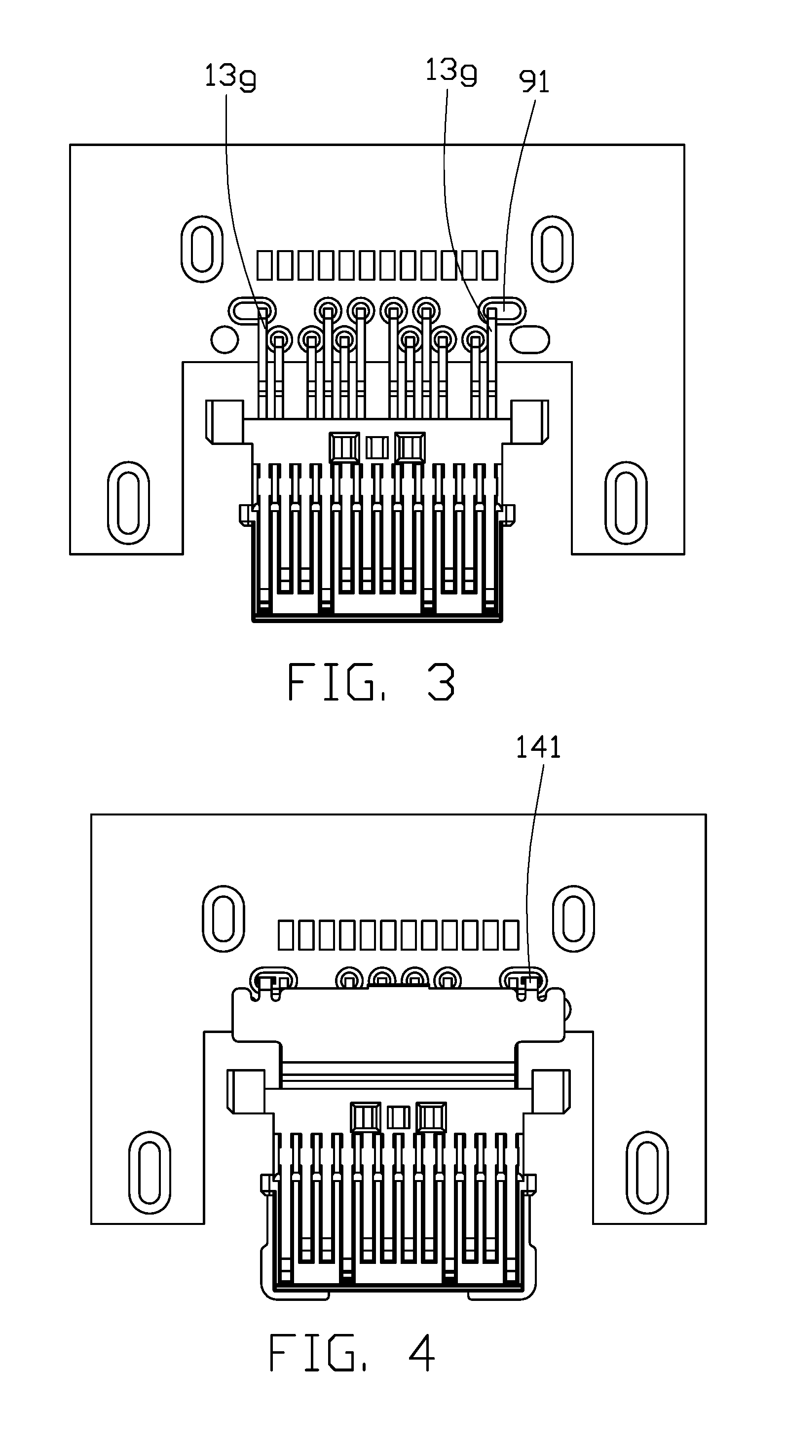
[0087]FIGS. 1-12 show a receptacle connector 100 mounted upon a printed circuit board 900 in a sink manner and a plug connector 200. As shown in FIGS. 1-7, the receptacle connector 100 includes an insulative housing with a mating tongue 101 enclosed in a metallic shell or EMI bracelet 12. A plurality of contacts 13 are disposed in the housing with contacting sections 132 exposed upon two opposite surfaces of the mating tongue 101. Understandably, the contacts 13 include the signal contacts, the grounding contacts and the power contacts thereof. A metallic shielding plate 14 is located at a middle level within the mating tongue 101 with edge portions extending out of the edges of the mating tongue for protection and locking consideration. The leg 141 of the shielding plate 14 and the tail 131 of the outmost grounding contact 13g extend into a same oval shaped via 91 of the printed circuit board 900. This common termination arrangement may achieve good signal transmission performance....

second embodiment

[0103]FIG. 28 shows a portable hard disk 50 equipped with an interface 501 of the plug connector as shown in the first or the second embodiment according o the invention, while the contact tails are mounted to an internal printed circuit board (not shown) therein. FIG. 29(A) shows a connector kit 51 with two spaced receptacle connectors according to the invention, stacked upon each other and integrally retained by a same housing wherein the mating ports 511 of the two receptacle connectors spaced from each other in the vertical direction with separation. FIG. 29(B) shows a connector kit 51 similar to that in FIG. 29(A) but with the two mating ports 512 are separated from each other via a partition wall 513 of the housing and each mating port 512 is hidden behind a front face of the housing. FIGS. 30(A) and 30(B) show the two connectors 521 / 522 similar to those in FIGS. 29(A) and 29(B) except in a side-by-side arrangement instead of a stacked manner. FIG. 31 shows a connector assembl...

third embodiment

[0106]Referring to FIGS. 41-43 showing the invention, the receptacle connector 65 includes a housing essentially composed of a straddle mounting upper housing 651 and a straddle mounting lower housing 652 commonly sandwiching therebetween a printed circuit board 653 which is essentially a mother board of a mobile device. A front edge region of the printed circuit board 653 defines a pair of cutouts / slots 6531 to form a mating tongue 654 therebetween. A plurality of circuit pads 6532 are formed on a front region of the mating tongue 650. The upper housing 651 and the lower housing 652 include two side walls 6511, 6521 extending into the corresponding slots 6531 to commonly form a mating port 655 in which the mating tongue 654 forwardly extends. The mating port of the plug connector 66 is mated with the mating port 655 wherein the center slot of the plug connector 66 receives the mating tongue 654, and the two opposite side wall of the housing of the plug connector 66 is received in t...


PUM


Abstract

A receptacle connector includes an insulative housing defining a base and a mating tongue extending from the base with a widen and thicken step structure formed around a root of the mating tongue near to the base, two rows of plate contacts disposed in the insulative housing with contacting sections exposed upon the mating tongue and in front of the step structure and categorized with signal contacts, power contacts and grounding contacts, and a metallic shielding plate disposed within a middle level of the mating tongue and occupying most portions of said mating tongue. The shielding plate defines a pair of immoveable and un-deflectable lateral edge sections in front of the step structure, each lateral edge section is configured to be adapted to be locked with a latch of a plug connector in a transverse direction.

Description

CROSS REFERENCE TO RELATED APPLICATIONS[0001]This application is a continuation of the co-pending application Ser. No. 14 / 558,732 filed on Dec. 3, 2014, and Ser. No. 14 / 839,880 filed on Aug. 28, 2014, the contents of which are incorporated entirely herein by reference.BACKGROUND OF THE INVENTION[0002]1. Field of the Invention[0003]The present invention relates to an electrical connector, and more particularly to a flippable plug connector used with a receptacle connector.[0004]2. Description of Related Art[0005]In the previously filed provisional applications, the plug connector is “flippable” whereas we turn the plug over and it functions the same top and bottom. In order to be able to handle switching of the super speed signaling, a MUX (or SS switch) is built into the silicon. This can be costly and also cause some additional degredation in the super speed signals.[0006]Hence, a new and simple electrical plug connector and the complementary receptacle connector are desired.SUMMAR...

Claims


Application Information

Patent Timeline
Patent Type & Authority Applications(United States)
IPC IPC(8): H01R24/60H01R13/66H01R13/627H01R13/658
CPCH01R24/60H01R13/658H01R2107/00H01R13/6275H01R13/665H01R13/6583H01R13/6587
Inventor LITTLE, TERRANCE F.CHENG, CHIH-PIKAO, CHIEN-PINGSU, WEI-HAOYANG, AN-JENZOU, DE-CHENGCHOU, CHIH-HSIENZHANG, YUAN
Owner FOXCONN INTERCONNECT TECHNOLOGY LIMITED
Learn More