Multi-mode lighting system with proximity sensor

a proximity sensor and lighting system technology, applied in lighting and heating apparatus, lighting applications, lighting support devices, etc., can solve problems such as troublesome manual switching of headlamps between modes, personal headlamp use, etc., and achieve the effect of reducing reflected light or glar

Active Publication Date: 2017-02-23
THE COLEMAN CO INC
View PDF0 Cites 18 Cited by
  • Summary
  • Abstract
  • Description
  • Claims
  • Application Information

AI Technical Summary

Benefits of technology

[0003]Some of the systems and techniques described herein include a lighting system capable of switching between lighting modes in response to user gestures or hand signals. In particular, the disclosure is directed to using a multitude of sensors to detect a direction of a hand movement, and changing modes of a lighting system based upon the detected direction of the hand movement. In accordance with at least some embodiments, the lighting system may cycle through lighting modes upon detecting a particular hand movement. Additionally, the disclosure discusses a lighting system capable of adjusting beam patterns automatically to reduce reflected light or glare. In particular, the lighting system may provide two or more light sources with different diffusion patterns. In some embodiments, reflected light from the two of more light sources may be detected and, in response to determining that the reflected light surpasses a threshold light level, one or more of the light sources may be extinguished.

Problems solved by technology

However, the use of personal headlamps also presents problems that are not typically experienced by flashlight users.
Additionally, having to manually switch a headlamp between modes can be problematic when the user's hands are dirty and / or slippery.

Method used


Image

  • Multi-mode lighting system with proximity sensor
  • Multi-mode lighting system with proximity sensor
  • Multi-mode lighting system with proximity sensor

Examples


Embodiment Construction

[0015]In the following description, various embodiments of the present invention will be described. For purposes of explanation, specific configurations and details are set forth in order to provide a thorough understanding of the embodiments. However, it will also be apparent to one skilled in the art that the present invention may be practiced without the specific details. Furthermore, well-known features may be omitted or simplified in order not to obscure the embodiment being described.

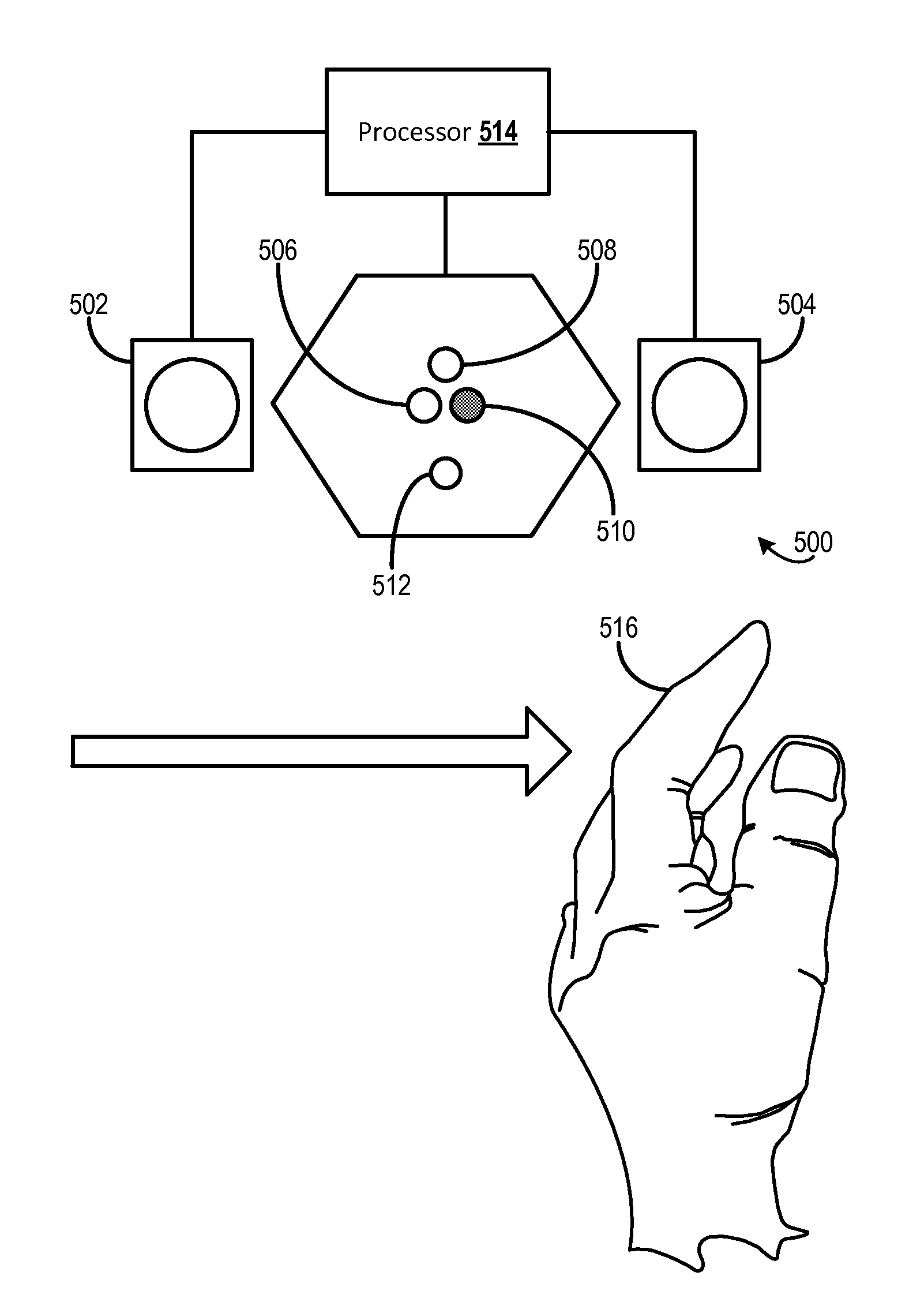
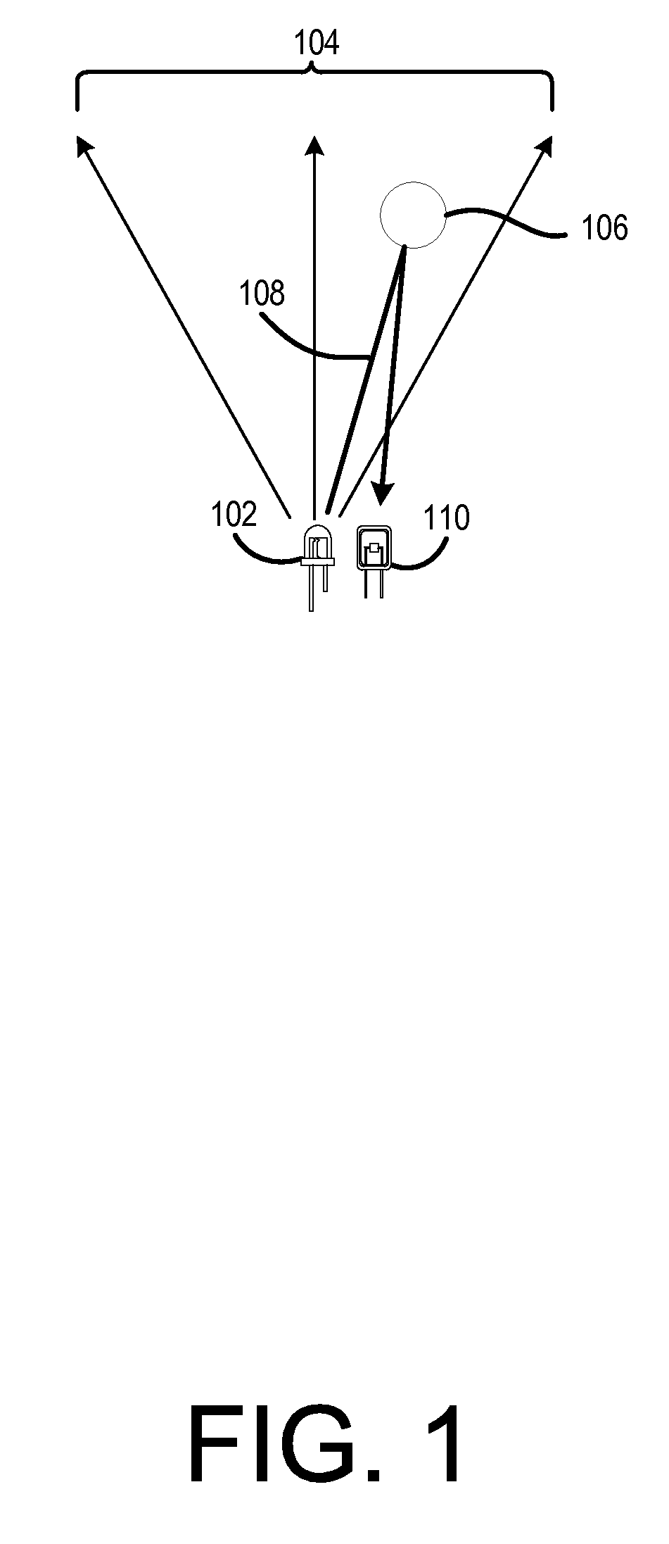
[0016]Some embodiments described herein are directed to a portable lighting device in which movement of and / or reflection from a proximate object may be detected, and a mode of the portable lighting device can be changed based upon the movement of the detected object. For example, FIG. 1 depicts a portable lighting device 102 from which electromagnetic radiation 104 is being emitted. Also depicted in FIG. 1 is an object 106 in proximity to the portable lighting device 102 and in the path of the el...


PUM


Abstract

Described herein is a lighting system capable of responding to user input provided via proximity sensors. In some embodiments, proximity sensors are communicatively coupled to a processor capable of receiving input from the sensors. The sensors may be arranged in a row such that an object moving down the row proximate to the sensors may trigger each sensor sequentially. In some embodiments, the lighting system may alter a beam configuration or cycle between various lighting modes in response to receiving input from the proximity sensors. In some embodiments, the order in which the sensor input is received may be used to determine which lighting mode to cycle to.

Description

BACKGROUND[0001]There are several situations in which a user may need to use a personal lighting system. In the past, flashlights have been extremely popular for use in these situations. However, recently users have begun to recognize the advantages of using a personal headlamp. For example, the use of a headlamp frees up a user's hands to allow the user to perform various tasks. However, the use of personal headlamps also presents problems that are not typically experienced by flashlight users. For example, when a user wearing the headlamp looks at a close object, light may be reflected into the eyes of that user. Additionally, having to manually switch a headlamp between modes can be problematic when the user's hands are dirty and / or slippery.BRIEF SUMMARY[0002]The following presents a simplified summary of some embodiments of the invention in order to provide a basic understanding of the invention. This summary is not an extensive overview of the invention. It is not intended to ...

Claims


Application Information

Patent Timeline
Patent Type & Authority Applications(United States)
IPC IPC(8): H05B37/02F21V23/04F21L4/02H05B44/00
CPCH05B37/0227F21V23/0414F21V23/0471F21L4/02F21W2111/10F21V21/084F21V21/145H05B47/115H05B47/13Y02B20/40
Inventor LAW, MATTHEW G.
Owner THE COLEMAN CO INC
Why Eureka
Try Eureka