Optical apparatus with loss compensation capability and optical amplifier for loss compensation

a technology of optical amplifier and optical apparatus, applied in the direction of semiconductor amplifier structure, electromagnetic transmission, semiconductor laser, etc., can solve the problems of large coupling loss of fiber with fiber than a fiber type device, high spatial coupling precision, and inability to integrate, so as to reduce the noise characteristic of optical amplifier and reduce the cost. , the effect of reducing the noise characteristic of the optical amplifier

Inactive Publication Date: 2006-06-13
FUJITSU LTD
View PDF20 Cites 14 Cited by
  • Summary
  • Abstract
  • Description
  • Claims
  • Application Information

AI Technical Summary

Benefits of technology

[0016]The present invention has been developed with the above-mentioned viewpoints taken into account, and aims at providing a technology for realizing an optical amplifier capable of obtaining a gain enough to compensating for a loss of various optical parts unlike the conventional optical amplifier in pursuit of high performance such as a high gain, a low NF (noise figure), etc., and obtaining a small and low-cost amplifier.
[0018]With the above-mentioned configuration, the connection position of the loss medium to the optical amplifier for performing loss compensation is prescribed, and the amount of reflection attenuation of the light at the connection point, etc. of the output side from the optical amplification unit is made smaller than the amount of reflection attenuation at the output terminal. As a result, at least the isolator at the output side between the isolators conventionally provided at the input side and the output side of the amplification medium can be omitted. Therefore, the apparatus can be smaller and realized at a lower cost. By increasing the loss of the loss medium, the reflected light on the output side of the optical amplification unit can be effectively reduced, thereby more widely setting the gain range in which no oscillation phenomenon occurs. Furthermore, by controlling the operation of the optical amplification unit based on the monitor result of the input light and the output light, the gain of the optical amplifier can be automatically adjusted although the amount of loss of the loss medium changes. As a result, the loss compensation of various optical parts having different amounts of loss can be realized by a small and low-cost optical amplifier.
[0020]Thus, by providing an isolator on the input side of the optical amplification unit, the noise light generated by the optical amplifier is prevented from being reflected by the input terminal and returned to the optical amplification unit. Therefore, although a high gain is set, the reduction of the noise characteristic of the optical amplifier can be suppressed.
[0021]In addition, the above-mentioned optical apparatus can be provided with a plurality of optical amplifiers corresponding to a plurality of loss media, and at least two of the plurality of optical amplifiers can be incorporated in parallel. Thus, the entire optical apparatus can be smaller at a lower cost.
[0022]Additionally, the above-mentioned optical apparatus can be provided with a plurality of optical amplifiers corresponding to a plurality of loss media, and at least two of the plurality of optical amplifiers can be incorporated in series. Thus, the gain of the entire apparatus can be improved, and the amount of loss to be compensated for in the entire apparatus can be distributed to each optical amplifier, thereby realizing a lower NF or higher efficiency for each optical amplifier.
[0023]The optical amplifier for loss compensation according to the present invention includes: an optical amplification unit provided between an input terminal and an output terminal; an input side monitor unit for monitoring the power of the light transmitted to the optical amplification unit; an output side monitor unit for monitoring the power of the light transmitted from the optical amplification unit to the output terminal; and a gain control unit for controlling the gain in the optical amplification unit based on each monitor result of the input side monitor unit and the output side monitor unit. A pair of loss medium connection points for connection of a loss medium are provided on the optical path between the output end of the optical amplification unit and the input end of the output side monitor unit. The configuration is determined such that the amount of reflection attenuation on all points, on which the light can be reflected on the optical path from the output end of the optical amplification unit to the output terminal, can be smaller than the amount of reflection attenuation on the end face of the output terminal. The gain control unit controls the operation of the optical amplification unit such that a gain at least equal to a loss generated in the loss medium connected to the loss medium connection points can be obtained. With the above-mentioned configuration, an optical amplifier for loss compensation is realized as a smaller and lower-cost device.

Problems solved by technology

Although a discrete type device can be downsized, it has a larger coupling loss with fiber than a fiber type device, and requires high spatial coupling precision.
Therefore, it is not appropriate for integration when a large number of configuration parts are used.
However, it has problems in characteristic such as a coupling loss with fiber, a polarization dependent loss (hereinafter referred to as a PDL), crosstalk, etc.
However, since this well-known technology does not provide a practical configuration appropriate for incorporating an optical amplifier to be downsized into a loss medium, it does not satisfy the request to a small optical amplifier for loss compensation as described above.
Nevertheless, the above-mentioned optical amplifier aims at only downsizing each optical amplifier basically by integration, but a practical configuration of an optical amplifier appropriate for integration with a loss medium is not realized.
Therefore, the request for a small optical amplifier for loss compensation is not completely satisfied.

Method used


Image

  • Optical apparatus with loss compensation capability and optical amplifier for loss compensation
  • Optical apparatus with loss compensation capability and optical amplifier for loss compensation
  • Optical apparatus with loss compensation capability and optical amplifier for loss compensation

Examples


first embodiment

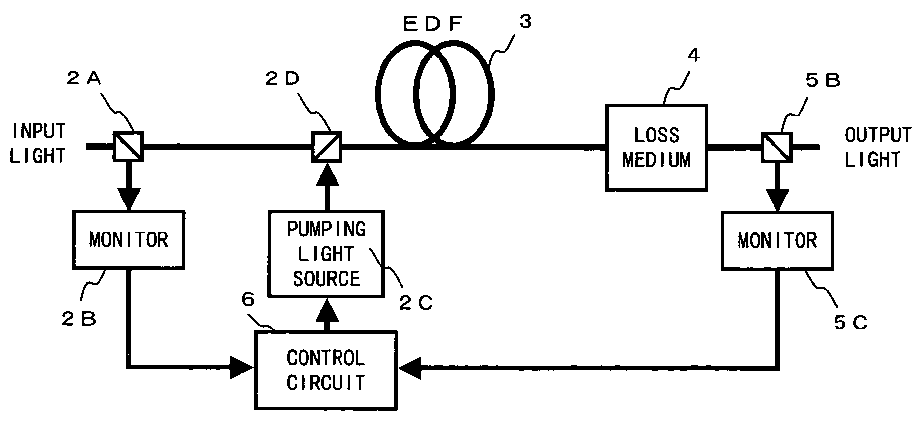
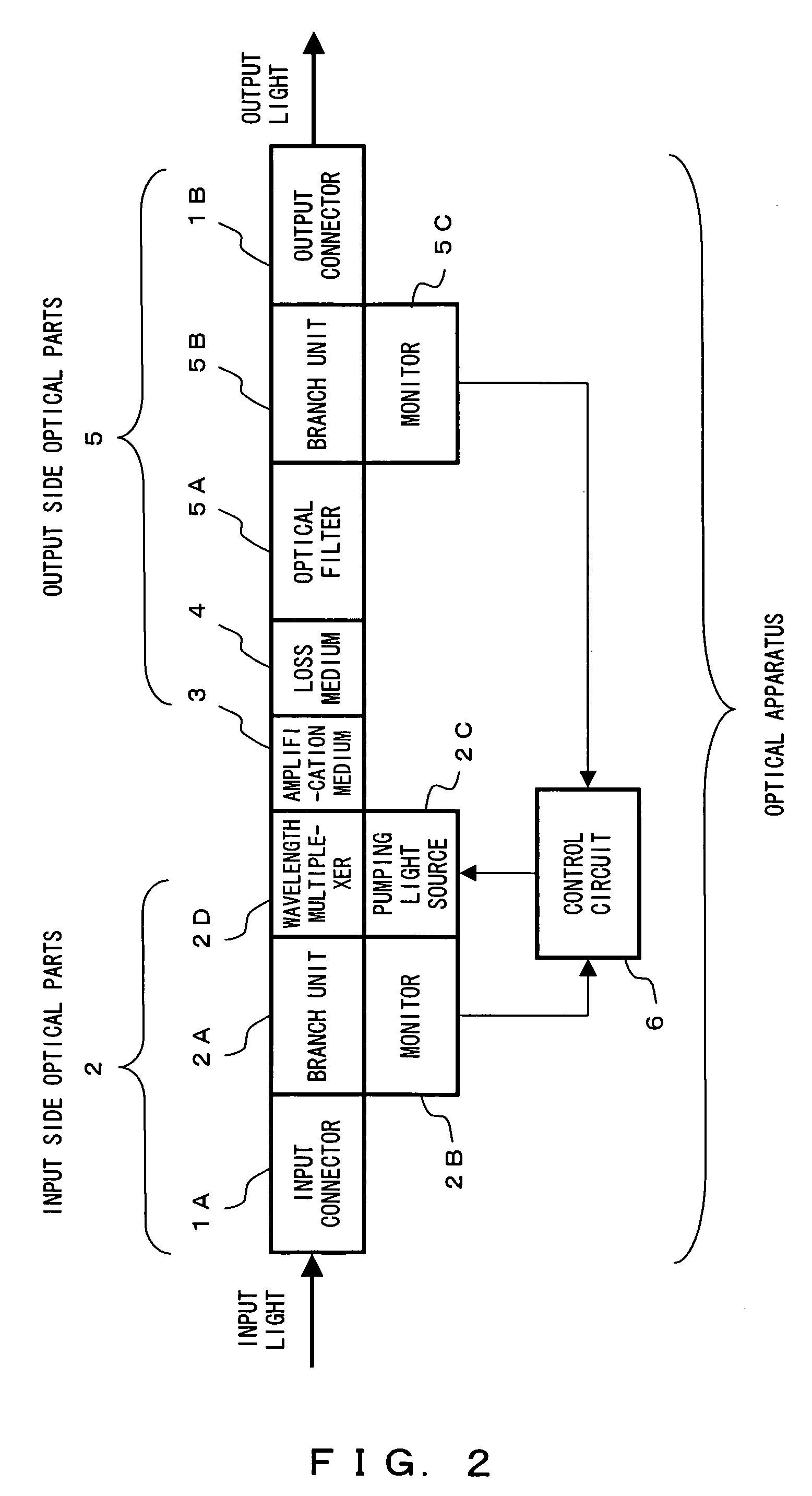
[0089]FIG. 2 shows a configuration of the optical apparatus having the loss compensation capability according to the present invention.

[0090]In FIG. 2, the optical apparatus comprises, for example, an input side optical parts 2, an amplification medium 3, a loss medium 4, and an output side optical parts 5 between an input connector 1A as an input terminal and an output connector 1B as an output terminal, and a control circuit 6 as a gain control unit for controlling the gain in the amplification medium 3.

[0091]The input side optical parts 2 comprises, for example, an input connector 1A; a branch unit 2A and a monitor 2B as an input side monitor unit for monitoring the power of the light input through the input connector 1A and transmitted to the amplification medium 3; and a pumping light source 2C and a wavelength multiplexer 2D for providing pumping light for the amplification medium 3. The branch unit 2A branches a part of the input light provided for the input connector 1A and ...

second embodiment

[0126]Described below is the optical apparatus having the loss compensation capability according to the present invention.

[0127]FIG. 13 shows the configuration of the second embodiment of the optical apparatus. The components similar to those according to the first embodiment are assigned the same reference numerals, and the explanation is omitted here, which also holds with other embodiments.

[0128]In FIG. 13, In the configuration of the optical apparatus according to the present embodiment, the portions different from those in the configuration of the first embodiment shown in FIG. 2 are represented by an input side optical parts 2′ for the input side optical parts 2. The input side optical parts 2′ is different from the input side optical parts 2 in that an isolator 2E is connected to the optical path between the branch unit 2A and the wavelength multiplexer 2D. The other components in the configuration are the same as those according to the first embodiment.

[0129]The isolator 2E ...

third embodiment

[0153]Described below is the optical apparatus having the loss compensation capability according to the present invention.

[0154]FIG. 23 shows an example of the outline of the configuration of the optical apparatus according to the third embodiment.

[0155]In FIG. 23, the optical apparatus according to the present embodiment can be further downsized and cost-reduced for an optical amplifier for loss compensation by incorporating a plurality of optical apparatuses according to the first embodiment into one system.

[0156]In this example, three optical amplifiers for loss compensation for three loss media 4A, 4B, and 4C are arrayed for each component, and the components capable of being collectively integrated are incorporated into an array structure.

[0157]The technology of collectively integrating various optical parts configuring each optical apparatus can be, for example, the optical waveguide technology, the integration through spatial coupling, the fiber array method, the fiber sheet ...


PUM


Abstract

An optical apparatus having a loss compensation capability includes between an input connector 1A and an output connector 1B an input side optical parts 2 including an input monitor, an amplification medium 3, a loss medium 4, and an output side optical parts 5 including an output monitor in this order, and is provided with a control circuit 6 for controlling a gain based on a monitor result of input / output light. The amount of reflection attenuation on all points, on which the light can be reflected on the optical path from the output end of the amplification medium 3 to the output connector 1B, can be smaller than the amount of reflection attenuation on the end face of the output connector 1B.

Description

CROSS REFERENCE TO RELATED APPLICATION[0001]This application is a continuation of an International application No. PCT / JP03 / 03106, which was filed on Mar. 14, 2003.BACKGROUND OF THE INVENTION[0002]1. Field of the Invention[0003]The present invention relates to an optical apparatus and an optical amplifier for use with an optical communications system, and more specifically to an optical apparatus provided with an optical amplification capability for compensation for a loss in a loss medium and a preferred optical amplifier for loss compensation.[0004]2. Description of the Related Art[0005]An optical amplifier is one of key components for realizing a long-distance and large-capacity optical communications system. Generally, an optical amplifier can be either a laser amplifier using stimulated emission from a population inversion medium or an amplifier based on a nonlinear optical effect such as Raman scattering, Brillouin scattering, etc. A laser amplifier can be an optical fiber amp...

Claims


Application Information

Patent Timeline
Patent Type & Authority Patents(United States)
IPC IPC(8): H01S3/00H01S3/067H01S3/13H01S3/131H01S5/0683H01S5/50
CPCH04B10/291H01S3/1305H01S3/1312H01S5/50H01S5/0683
Inventor NAKASHIMA, HISAOONAKA, MIKINISHIHARA, MASATOHAYASHI, ETSUKOMIYATA, HIDEYUKI
Owner FUJITSU LTD
Why Eureka
Try Eureka