Antireflection film

Inactive Publication Date: 2015-04-30
SOKEN CHEM & ENG CO LTD
View PDF4 Cites 15 Cited by
  • Summary
  • Abstract
  • Description
  • Claims
  • Application Information

AI Technical Summary

Benefits of technology

[0032]In still another aspect of the antireflection film according to the present invention, the antireflection film can be arranged between, for example, an information display module an

Problems solved by technology

However, in the display device, when outside light such as sunlight or room lighting enters the screen, a part of the light is reflected by the screen to deteriorate contrast on the screen and disadvantageously whiten the screen.
Thus, reflected light (white light) overlaps the image displayed on the liquid crystal display panel 12 to decrease contrast of the image, thereby deteriorating display quality.
When the optical projections are flattened out in this manner, the antireflection function of the antireflection film is deteriorated and damaged.
However, when the conical protective pillars are used, the tops of the pillars are easily flattened when the protective pillars are depressed with a surface facing the protective pillars.
However, since the protective pillars cannot have antireflection structures formed thereon, when the areas of the top surfaces of the protective pillars are increased, the optical performance of the

Method used


Image

  • Antireflection film
  • Antireflection film
  • Antireflection film

Examples


first embodiment

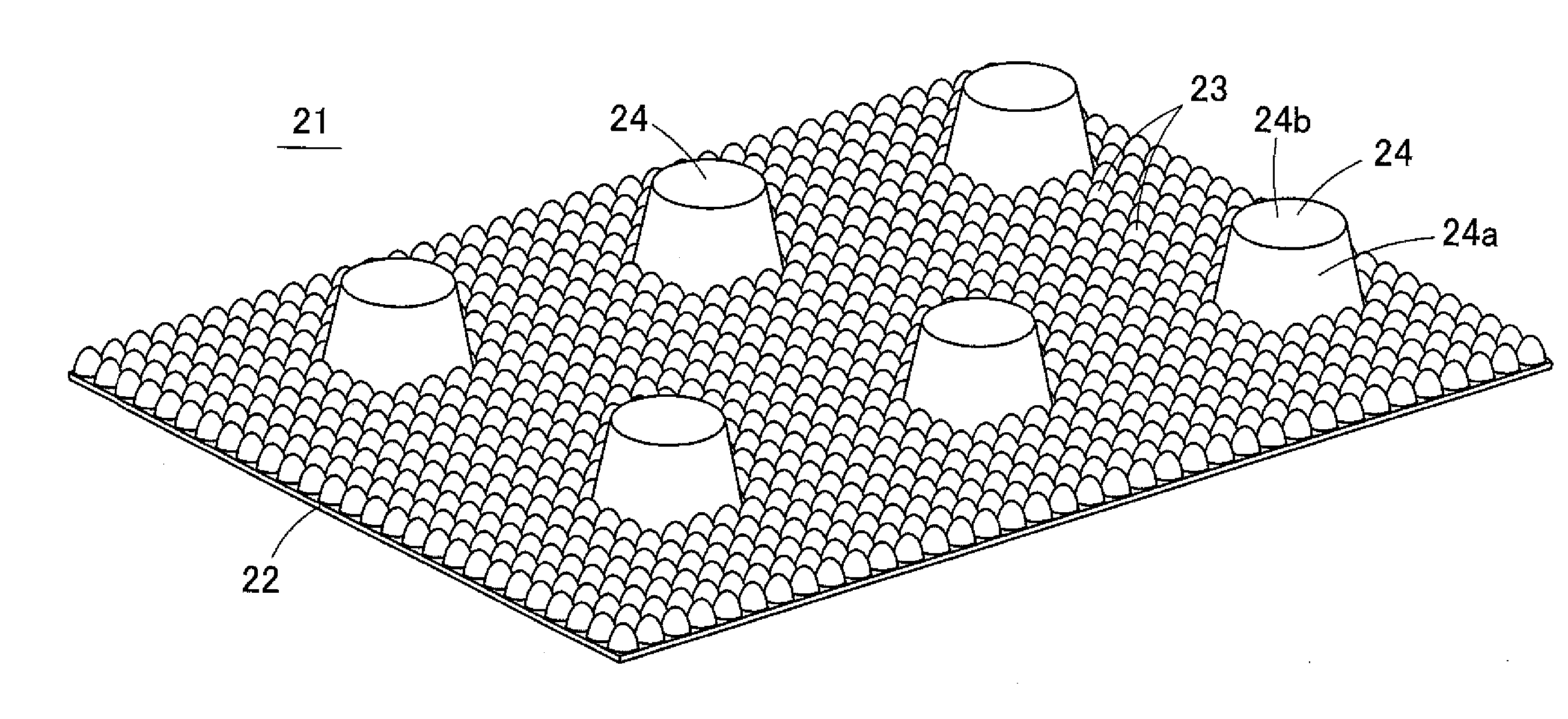
[0060]FIG. 5 is a partially enlarged perspective view showing an antireflection film 21 according to a first embodiment of the present invention. FIG. 6 is a sectional view showing a section passing through the central axis of its protrusion, i.e., a protective pillar 24. As shown in FIG. 5, the antireflection film 21 is formed such that, on a smooth surface of a transparent film base material 22, a large number of transparent optical projections 23 having a refractive index equal to that of the film base material 22 are densely formed. On the surface of the film base material 22, transparent protective pillars 24 (protrusions for preventing tight contact) each having a truncated cone shape and a refractive index equal or almost equal to that of the film base material 22 are arranged at a predetermined pitch.

[0061]The film base material 22 is made of a transparent resin having a large refractive index such as a polycarbonate resin or an acrylate resin and shaped in the form of a pla...

second embodiment

[0070]An antireflection film 31 according to a second embodiment of the present invention will be described below. FIG. 9 is a partially enlarged perspective view of the antireflection film 31 according to the second embodiment of the present invention. The antireflection film 31 is formed such that, on a smooth surface of a transparent film base material 22, a large number of transparent optical projections 23 having a refractive index equal to that of the film base material 22 are densely formed. On the surface of the film base material 22, transparent protective pillars 24 (protrusions for preventing tight contact) each having a truncated cone shape and a refractive index equal or almost equal to that of the film base material 22 are arranged at a predetermined pitch.

[0071]The film base material 22 is made of a transparent resin having a large refractive index such as a polycarbonate resin or an acrylate resin and shaped in the form of a plate. The film base material 22 may be a ...


PUM


Abstract

On a surface of a film base material (22), an antireflection structure configured by nano-sized optical projections (23) to suppress reflection of light and protective pillars (24) to prevent the optical projections (23) from being flattened out are arranged. The protective pillar (24) has a truncated cone shape. When a diameter of the protective pillar (24) at a proximal end thereof, a height of the protective pillar (24), and an angle between a side surface of the protective pillar (24) and a central axis of the protective pillar (24) on a section passing through the central axis of the protective pillar (24) are given by D, H, and θ, respectively, these values satisfy a relationship: D>2H×tan(2θ).

Description

TECHNICAL FIELD[0001]The present invention relates to an antireflection film. The present invention relates to an antireflection film that is used in, for example, a display device to prevent reflections of sunlight, room lighting, disturbance light, and the like and to improve the visibility of a screen so as to cause the screen to be clearly seen.BACKGROUND ART(Operation of Antireflection Film)[0002]Various devices such as a mobile phone, a mobile computer, and a personal computer include display devices that can display high-definition image. However, in the display device, when outside light such as sunlight or room lighting enters the screen, a part of the light is reflected by the screen to deteriorate contrast on the screen and disadvantageously whiten the screen.[0003]Such a phenomenon in which outside light is reflected occurs as shown in FIG. 1A, for example. FIG. 1A shows a display device 11 in which a cover panel 13 is superposed on the front surface of a liquid crystal ...

Claims


Application Information

Patent Timeline
IPC IPC(8): G02B1/118G02F1/1333G02F1/1335
CPCG02B1/118G02F1/13338G02F1/133502G02F2201/38
Inventor OSUMI, YOSHIMASANAKAGAWA, TAKEHIKOMINOBE, TETSUYAYAMAMOTO, YUKIITO, YOSHINORITAKAGI, YOSHIHIKO
Owner SOKEN CHEM & ENG CO LTD
Why Eureka
Try Eureka