Optical alignment method and apparatus

a technology of optical alignment and optical isolator, which is applied in the field of optical bidirectional transceivers, can solve the problems of increasing the manufacturing cost the difficulty of minimizing the size of the difficulty of applying the optical isolator to the optical transceiver module for a subscriber network application requiring low cost and small size, so as to save the alignment task time and achieve the effect of low cos

Inactive Publication Date: 2007-06-14
ELECTRONICS & TELECOMM RES INST
View PDF9 Cites 16 Cited by
  • Summary
  • Abstract
  • Description
  • Claims
  • Application Information

AI Technical Summary

Benefits of technology

[0013] Therefore, the present invention has been made in view of the above problems, and it is an object of the present invention to provide an optical alignment method, of a bidirectional optical transmitter for transmitting and receiving an optical signal bidirectionally through a single optical fiber, of reducing RIN generated by reflected light by reducing the reflected light input and of guaranteeing high optical coupling efficiency, and an apparatus for performing the same.
[0019] Once the ratio value is set following above process, for the other production of transceiver modules hereafter, the alignment process is carried out by just measuring the mPD output current at the maximum output position and defocusing the optical fiber to the position that predetermined mPD current ratio value comes out. By doing so, the present invention saves the alignment task time that the RIN meter consumes a lot due to digital signal process inside and the cost since manufacturers can carry out alignment process without high cost RIN meter by just taking the optical mPD current ratio value determined in previous step instead of real time RIN measurement during alignment process.

Problems solved by technology

However, since the optical isolator is expensive, manufacturing costs of the optical transceiver module increase.
Moreover, since the optical isolator is implemented in the form of bulk type, it is difficult to minimize the size of the optical transceiver module.
Thus, it is more difficult to apply the optical isolator to an optical transceiver module for a subscriber network application requiring low costs and small size.

Method used


Image

  • Optical alignment method and apparatus
  • Optical alignment method and apparatus
  • Optical alignment method and apparatus

Examples


Embodiment Construction

[0032] Hereinafter, the present invention will be described in detail with reference to the accompanying drawings as follows. It is noticed that like reference numerals designate like or corresponding components throughout the several drawings. Moreover, in the following description of the present invention, if the detailed description of the already known structure and operation may confuse the subject matter of the present invention, the detailed description thereof will be omitted.

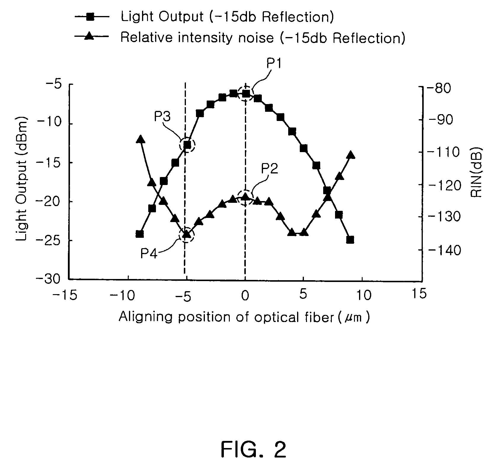
[0033] The present invention is different from the conventional method and apparatus and is intended to carrying out an optimal optical alignment by taking the maximum light output and the minimum RIN into consideration. In an optical transceiver module without an isolator, at an optical alignment position indicating the maximal light output, where the RIN is also maximal by experiment. The optical alignment is carried out based on the maximum output by adjusting a focus of an optical axis, and then th...


PUM


Abstract

In disclosed optical alignment method and apparatus thereof, external reflection entering laser diode by feedback from transmission line of low cost bidirectional optical transceiver module without optical isolator for subscribers is reduced so as to reduce RIN considering high optical coupling efficiency. The external reflection is minimized using property that output current increases in proportion to external reflection during optical alignment. For optimal optical alignment, external reflection and RIN are previously measured according to optical alignment position between subassembly and optical fiber. Optimal position is determined by both light output and RIN, and predetermined ratio of the mPD output current of minimum RIN position to that of maximum light output power position.

Description

RELATED APPLICATION [0001] The present application is based on, and claims priority from, Korean Application Number 2005-120237, filed Dec. 8, 2005, and Korean Application Number 2006-62679, filed Jul. 4, 2006, the disclosure of which is incorporated by reference herein in its entirety. BACKGROUND OF THE INVENTION [0002] 1. Field of the Invention [0003] The present invention relates to an optical bidirectional transceiver for transmitting and receiving an optical signal bidirectionally through a single optical fiber, and more particularly, to an optical alignment method of reducing light input reflected from a certain end point on a transmission line and entering a laser diode to reduce a Relative intensity noise (RIN) generated by the reflected light and to secure optical coupling efficiency at the same time, and an optical alignment apparatus. [0004] 2. Description of the Related Art [0005] RIN occurring in an optical transceiver module increases in proportion to the quantity of r...

Claims


Application Information

Patent Timeline
Patent Type & Authority Applications(United States)
IPC IPC(8): G02B6/36
CPCG02B6/4204G02B6/4227G02B6/42G02B6/43
Inventor LEE, JONG JINKANG, HYUN SEO
Owner ELECTRONICS & TELECOMM RES INST
Why Eureka
Try Eureka