
Low-Reflectance Self-Illumination Unit Display

a self-illumination unit and low-reflectance technology, applied in the direction of discharge tube luminescnet screens, discharge tube/lamp details, electric discharge lamps, etc., can solve the problems of reducing the contrast, the current challenge of reducing the reflection of ambient light, etc., to reduce the ambient light entering the non-light-emitting area of the display substrate, enhance the contrast of image, and reduce the reflection light

Inactive Publication Date: 2008-02-21
AU OPTRONICS CORP
View PDF6 Cites 14 Cited by
  • Summary
  • Abstract
  • Description
  • Claims
  • Application Information

AI Technical Summary

Benefits of technology

[0012]The amount of ambient light getting into the non-light-emitting area of the display substrate can be reduced through disposing the light-absorbing structure, and thereby reduce the reflecting light caused by the driving circuit unit reflecting the ambient light. The configuration of the light modulation layer can reduce the amount of ambient light getting into the display substrate to enhance the contrast of image created by light emitting out of the self-illumination unit. Moreover, through the collocation of the light modulation layer and the light-absorbing structure, the amount of reflecting light generated by incident ambient light can be reduced effectively to achieve the effect of enhancing the display contrast.

Problems solved by technology

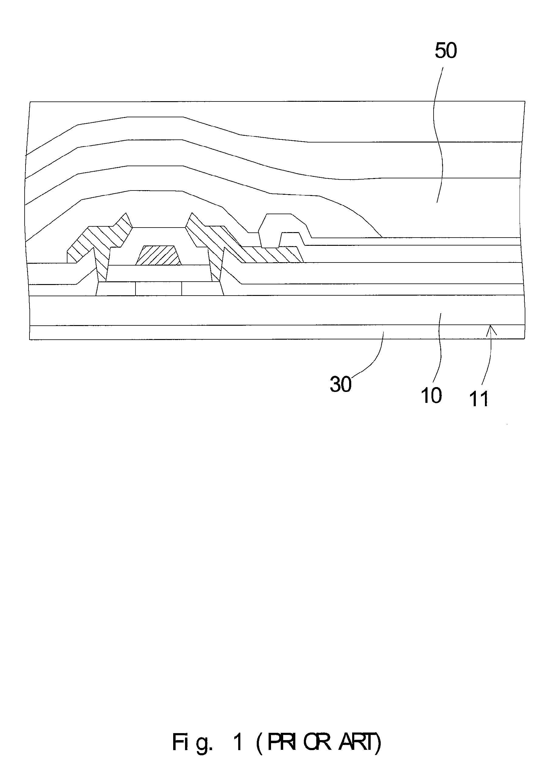
Since ambient light enters into the display panel from the display and reflects out of the display through electrode or transistor elements within the display panel, the reflecting light constantly affects the performance of light originally emitting out of the display panel and brings about the reduced contrast.
Therefore, how to reduce the reflection of ambient light becomes a current challenge.

Method used


Image

  • Low-Reflectance Self-Illumination Unit Display
  • Low-Reflectance Self-Illumination Unit Display
  • Low-Reflectance Self-Illumination Unit Display

Examples


Embodiment Construction

[0021]The present invention provides a self-illumination unit display. In the preferred embodiment, the self-illumination unit display of the present invention includes a color organic light emitting diode (OLED) display. However, in other embodiments, the self-illumination unit display of the present invention may be a monochromatic OLED display. In still other embodiments, the self-illumination unit display of the present invention may also include a high polymer OLED display. The self-illumination unit display of the present invention can be applied to various panel displays, household flat panel TV, flat panel monitor for desktop and laptop, and display screen for cellular phone and digital camera.

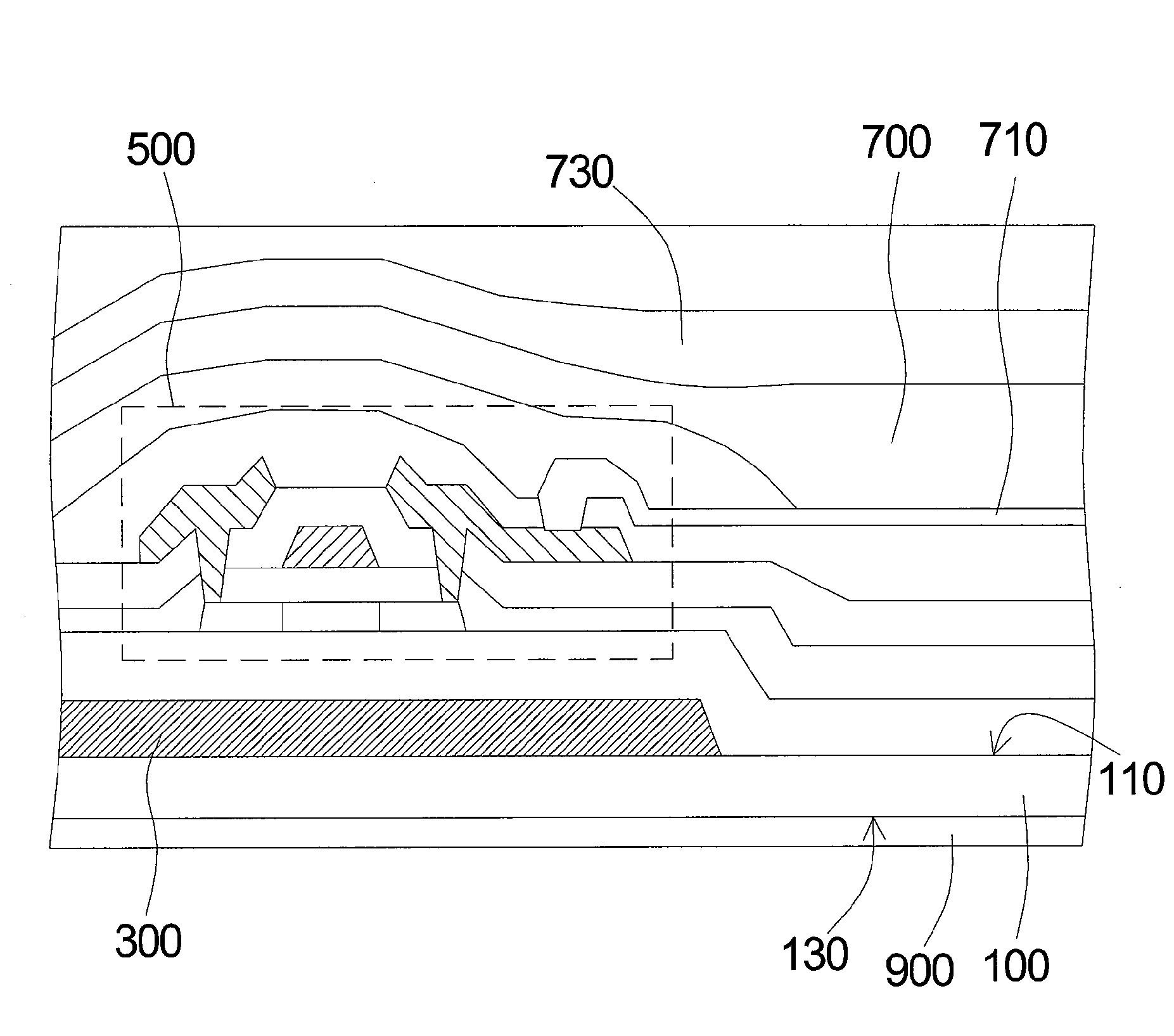
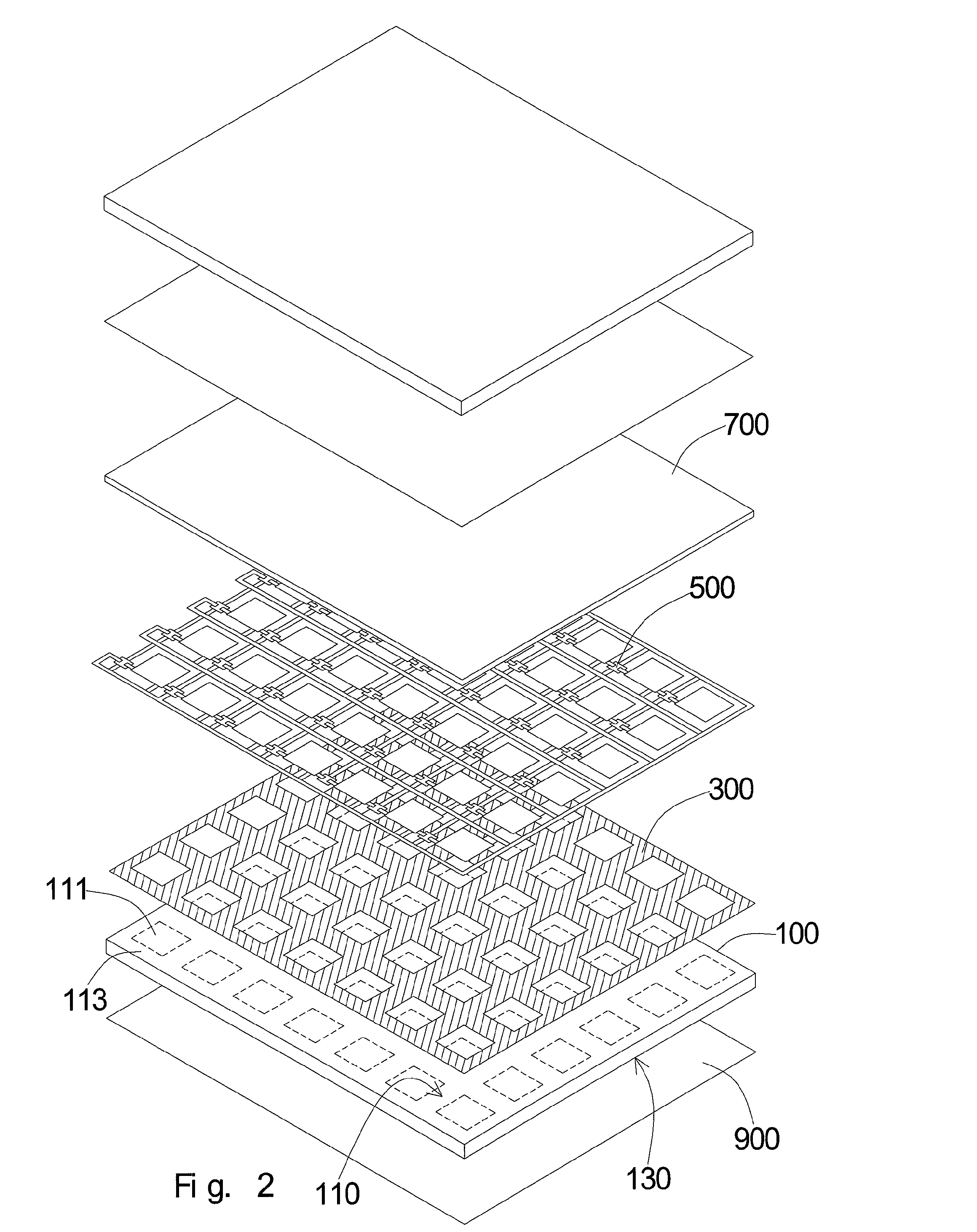
[0022]In the preferred embodiment shown in FIG. 2, the self-illumination unit display comprises a display substrate 100, a light-absorbing structure 300, a driving circuit unit 500, a self-illumination unit 700 and a light modulation layer 900. The display substrate 100 has an inner su...


PUM


Abstract

The present invention provides a self-illumination unit display comprising a display substrate, a light-absorbing structure, a driving circuit unit, a self-illumination unit and a light modulation layer. The light-absorbing structure, the driving circuit unit and the self-illumination unit are all formed on the inner surface side of the display substrate, while the light modulation layer is preferably formed on the outer surface of the display substrate. The light-absorbing structure is formed on the inner surface of the display substrate, and is substantially located within the non-light-emitting area. The driving circuit unit is located above the light-absorbing structure. The self-illumination unit is substantially located within the light-emitting area. The light modulation layer is disposed on the outer surface of the display substrate. The light transmittance of the light modulation layer is approximately greater than 42%.

Description

BACKGROUND[0001]1. Field of the Invention[0002]The present invention relates generally to a self-illumination unit display, and more particularly to a low-reflectance self-illumination unit display.[0003]2. Description of the Prior Art[0004]With the increasing demand for thin-type displays, the technology advancement of the self-illumination unit display becomes more and more important. The technology of self-illumination unit display including organic light emitting diode (OLED) display is getting mature as well. For example, for OLED display, the display panel brightness and contrast is usually the main consideration to evaluate the overall quality. Hence, in the display field for the time being, how to effectively enhance the utilization rate of light emitting out of the self-illumination unit has become a major goal.[0005]With respect to the display contrast, the overall color and the image performance of the display panel is more desirable when the contrast is high. However, in...

Claims


Application Information

Patent Timeline
Patent Type & Authority Applications(United States)
IPC IPC(8): H05B33/00H01L51/50H05B33/06
CPCH01L27/322H01L51/5284H01L51/5281H10K59/38H10K59/8792H10K50/86H10K50/865
Inventor LI, SHI-HAO
Owner AU OPTRONICS CORP
Learn More