Slip resistant mat with stabilizing projections

Active Publication Date: 2017-03-02
CINTAS CORP SERVICES INC
View PDF4 Cites 9 Cited by
  • Summary
  • Abstract
  • Description
  • Claims
  • Application Information

AI Technical Summary

Benefits of technology

[0012]One advantage of the invention is that the mat resists slipping to a much greater extent than existing mat designs. Another advantage of the invention is that the edges of the mat are more stable and therefore it is less of a tripping hazard or obstacle than traditional mats in which the edge of the mat easily rolls up onto or under the mat. Another advantage is that the mat of this invention provides the enhanced slip-resistance without adding any weight or installation complexity. Another advantage is that the invention does not require any permanent fastening means and is therefo

Problems solved by technology

However, both of these approaches resulted in floor mats that were not skid resistant on smooth floors, especially those floors with high traffic areas or loads being moved over them.
For the smooth back mats, movement of the mat results from similar forces and the lack of any device or feature intended to secure the mat in place.
While this approach is well-developed, it results in floor mats that are difficult or impossible to move from place to place and the structures required to attach the mat add cost to the mat and difficulty during the installation.
If the frame is fastened or embedded, the other problems mentioned above still remain including particularly the ability to relocate the mat to a dif

Method used


Image

  • Slip resistant mat with stabilizing projections
  • Slip resistant mat with stabilizing projections
  • Slip resistant mat with stabilizing projections

Examples


Example

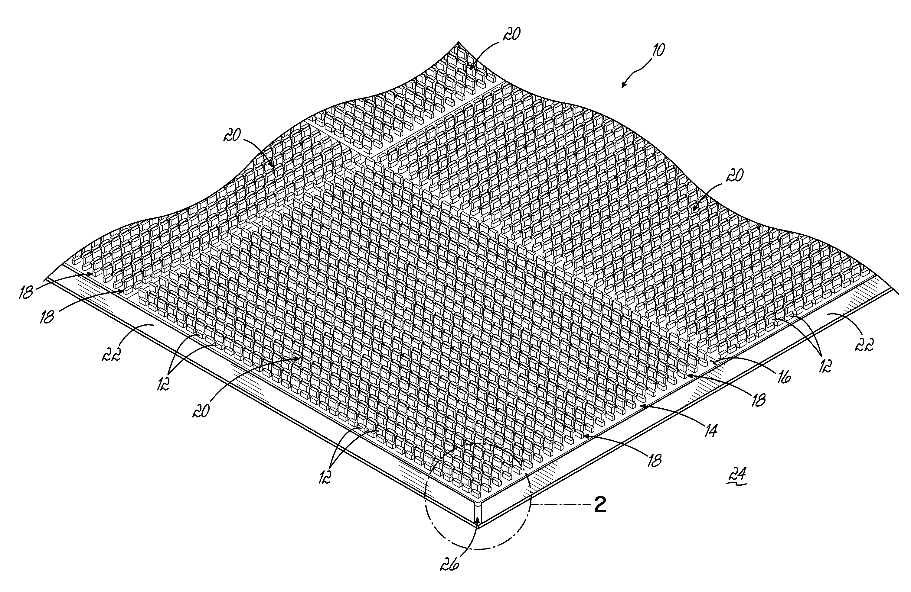
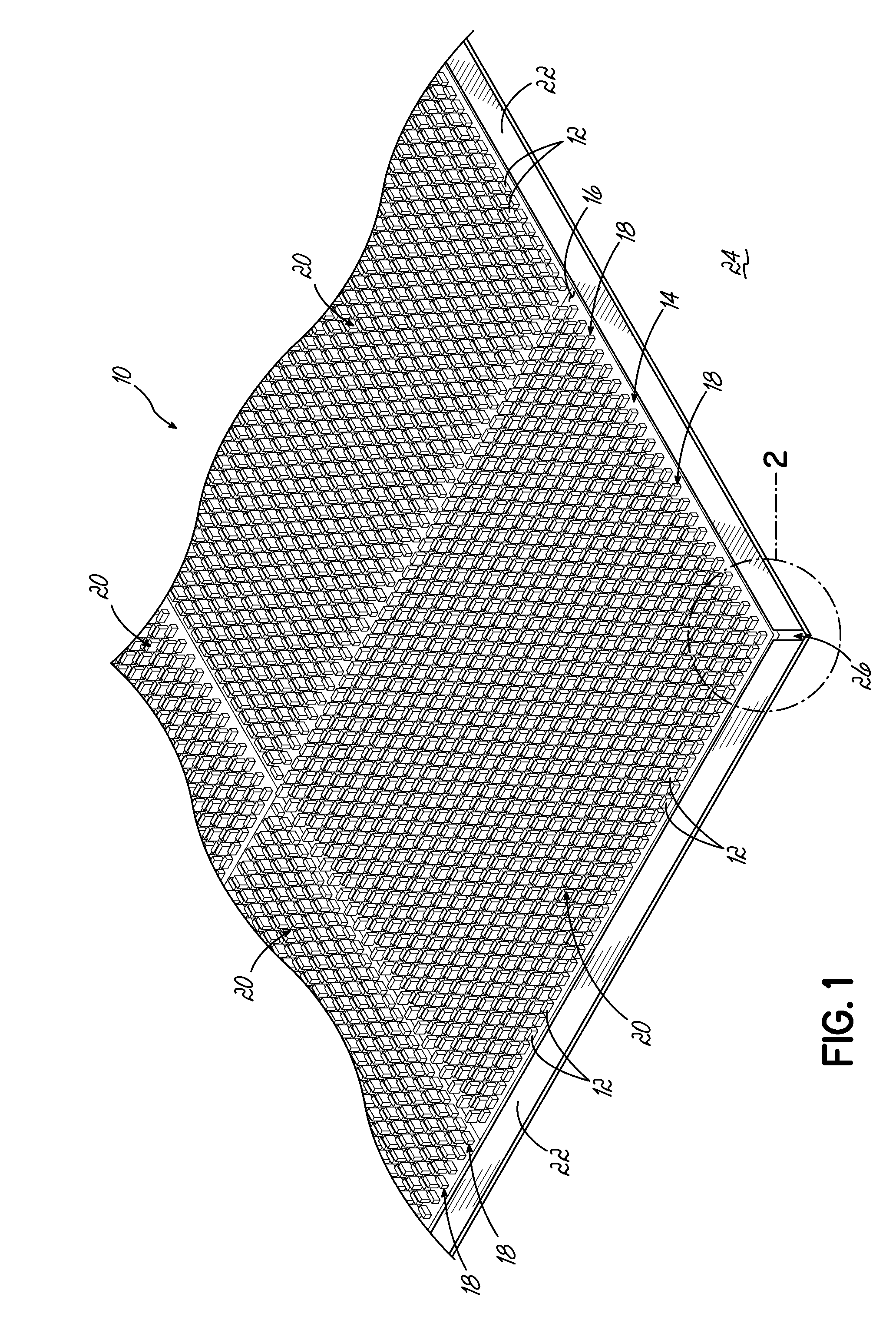
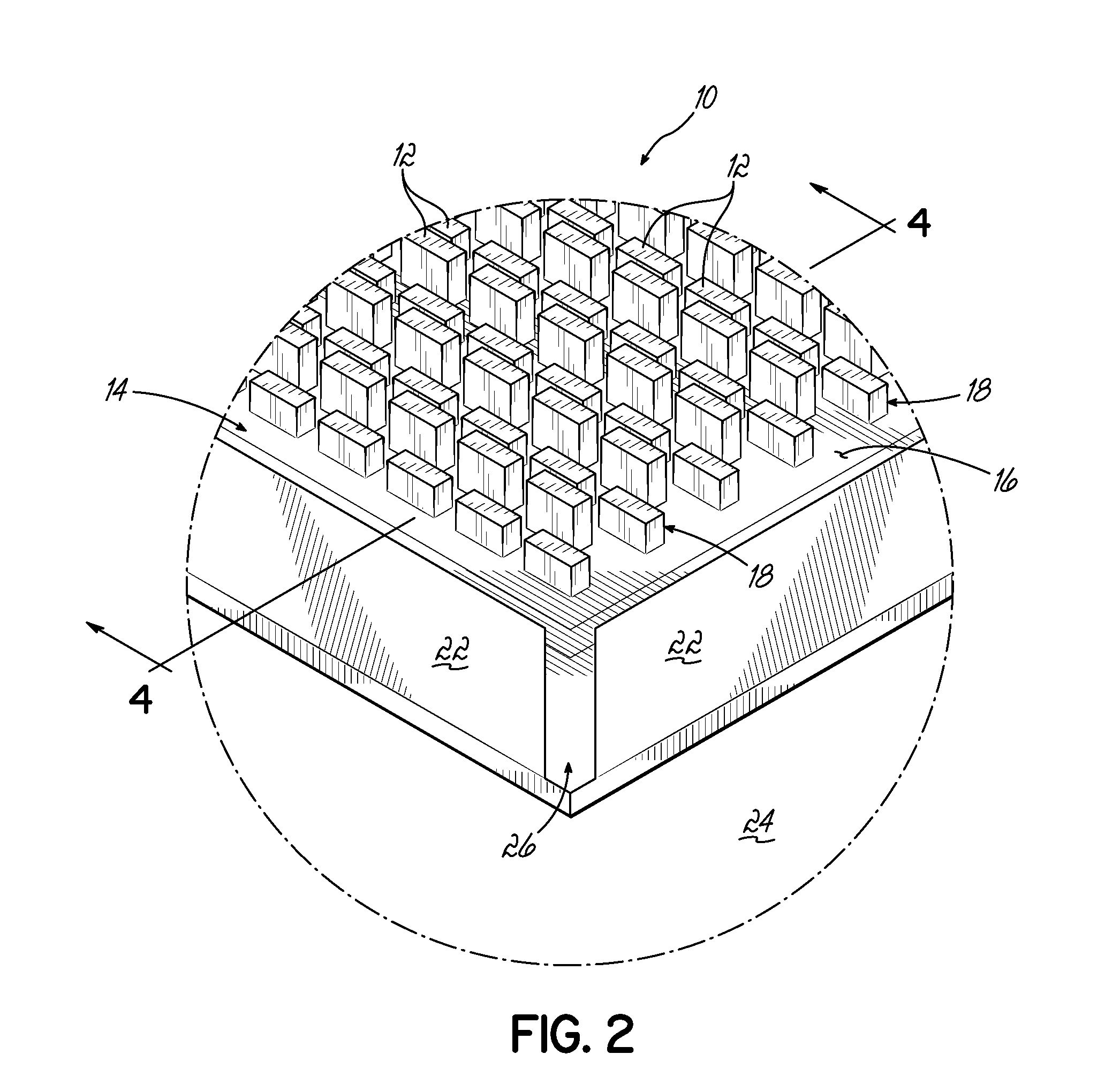
[0018]Referring to FIG. 1, one embodiment of a slip-resistant mat 10 with stabilizing projections 12 according to this invention is shown. The mat 10 includes a mat body 14 having an upper surface 16. A number of projections 12 extend upwardly from the upper surface 16 of the mat body 14. The projections 12, according to various embodiments of this invention, are arranged in multiple-spaced rows 18, and are similarly oriented in one embodiment of this invention. In various embodiments of this invention, the projections 12 may be arranged in an orderly consistent uniform arrangement, at least in portions of the mat 10. In alternative embodiments of this invention, the projections 12 are arranged in sections, or quadrants 20, with the orientation of the projections 12 and the rows 18 being generally perpendicular to the orientation of the projections 12 and rows 18 in adjacent quadrants 20 or sections of the mat 10. This arrangement is readily seen in FIG. 1.

[0019]The mat 10 includes ...


PUM


Abstract

A slip resistant floor mat includes a number of upstanding projections in the form of blades or teeth arranged on an upper surface thereof. The blades or teeth deflect under a load and dissipate the force of the load so that the tendency of the mat to slip on the underlying floor is reduced.

Description

[0001]This claims the benefit of U.S. Provisional Patent Application Ser. No. 62 / 209,379, filed Aug. 25, 2015 and hereby incorporated by reference in its entirety.BACKGROUND OF THE INVENTION[0002]This invention relates generally to floor mats and, more particularly, to a floor mat which resists slipping relative to the underlying floor when a force is applied to the top of the mat such as a foot step, rolling cart or similar interaction.[0003]In the past, floor mats were often made with either a smooth back, primarily for solid or non carpeted floors, or with a variety of “grippers” or “cleats” arranged on a bottom surface of the mat to reduce movement of the mat on carpeted floors. However, both of these approaches resulted in floor mats that were not skid resistant on smooth floors, especially those floors with high traffic areas or loads being moved over them. The movement of the mat in the gripper / cleat mat design results from the force of foot, vehicle and other traffic on the ...

Claims


Application Information

Patent Timeline
IPC IPC(8): A47G27/02
CPCA47G27/0212A47G27/0231Y10T428/24182
Inventor BING, RICHARD R.CHILENSKI, PATRICK J.COFER, JEFFERY L.MALPASS, IAN S.MESKO, DAVID
Owner CINTAS CORP SERVICES INC
Why Eureka
Try Eureka