Input selective smart bias tee

a smart bias and input technology, applied in the direction of antenna details, antennas, electrical equipment, etc., can solve the problems that conventional smart bias tees cannot be used to convey power to tower-mounted equipment using such connectors, and the control signals of tower-mounted equipment become more complex with multi-band antennas

Inactive Publication Date: 2017-03-02
COMMSCOPE TECH LLC
View PDF3 Cites 2 Cited by
  • Summary
  • Abstract
  • Description
  • Claims
  • Application Information

AI Technical Summary

Benefits of technology

[0008]The Invention comprises an Interface for powering and controlling an antenna, having an RF signal input, an AISG signal input, including a DC current, wherein the RF signal input is coupled to the antenna by a filter, so the filter blocks a signal with DC current, and the AISG signal is cou

Problems solved by technology

Using SBTs to provide DC power and control signals to tower-mounted equipment becomes more complex with multi-band antennas.
In particular, a current issue is that there are certain advantages to employing a standard antenna interface that utilizes blind mate, capacitively coupled, coaxia

Method used


Image

  • Input selective smart bias tee
  • Input selective smart bias tee
  • Input selective smart bias tee

Examples


Embodiment Construction

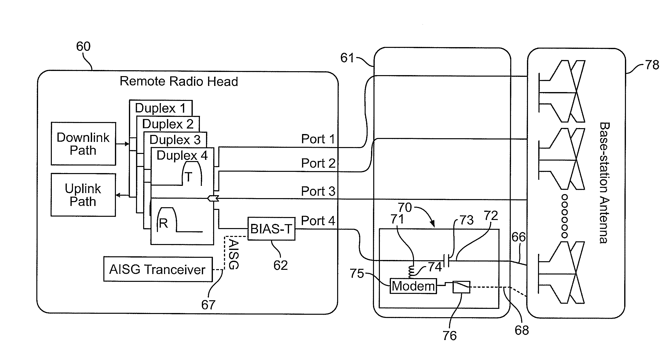
[0017]A wireless communications Base Station is illustrated in FIGS. 7 and 8 and can include a Remote Radio Head 60, a Interface 61 including an Input Selective Smart Bias Tee 62, and a RET Antenna 63 having an AISG controller 64. The Input Selective SBT 62 includes an RF Input 65, an RF output 66 to the Antenna 78, an AISG Input 67, and an AISG Output 68. While “input” and “output” are used herein with reference to a control data flow from the Remote Radio Head 60 to a RET Antenna 63, a person of ordinary skill would understand that the data transmission is bidirectional, and that data also flows from the RET Antenna 63 back to the Remote Radio Head 60.

[0018]Referring to FIG. 3, one example of a Antenna Interface that may be used in the subject invention 110 is disclosed. In this example, an Upper Tower Mount 112, and Middle Tower Mount 114 and a Lower Tower Mount 116 are mounted on a Mounting Pole 118. The Upper Tower Mount 112, and Middle Tower Mount 114 and a Lower Tower Mount 1...


PUM


Abstract

The Invention comprises a method and Interface for powering and controlling an antenna, having an RF signal input, an AISG signal input, including a DC current, wherein the RF signal input is coupled to the antenna by a filter, so the filter blocks a signal with DC current, and the AISG signal is coupled to the antenna through a switch, so that if an AISG signal is present, the switch automatically allows the AISG signal through to the antenna for control of the antenna, and if no AISG signal is present, the RF signal is automatically allowed through to the antenna for control of the antenna.

Description

[0001]This application claims priority from U.S. provisional application Ser. No. 61 / 943,156, filed Feb. 21, 2014.[0002]Smart Bias Tees (SBT) are often used inside antennas to allow power and control signals for an actuator to be transmitted to the antenna via an RF coax cable rather than a separate multi-conductor cable. At the base of the tower, a first SBT puts the power and control onto the RF cable. At the top of the tower, a second SBT pulls it back off See, for example, US Pat. App. Pub. No. 2007 / 0161348 (the “348 Application”), which is incorporated by reference.[0003]A known application of SBTs is illustrated in FIG. 1. An electrical downtilt of an antenna beam may be controlled by a Remote Electrical Tilt (RET) device 15. A Base Station may comprise three or more such antennas mounted on a tower. A system 10 comprises a control subsystem 16 which interfaces with the RETs 15, a radio 17 which interfaces with the antennae 13, and a DC power supply 18 which provides DC power ...

Claims


Application Information

Patent Timeline
IPC IPC(8): H01Q1/24H01Q1/12
CPCH01Q1/1228H01Q1/246
Inventor BUTLER, RAY K.PATEL, SAMMITBUONDELMONTE, CHARLES
Owner COMMSCOPE TECH LLC
Why Eureka
Try Eureka