
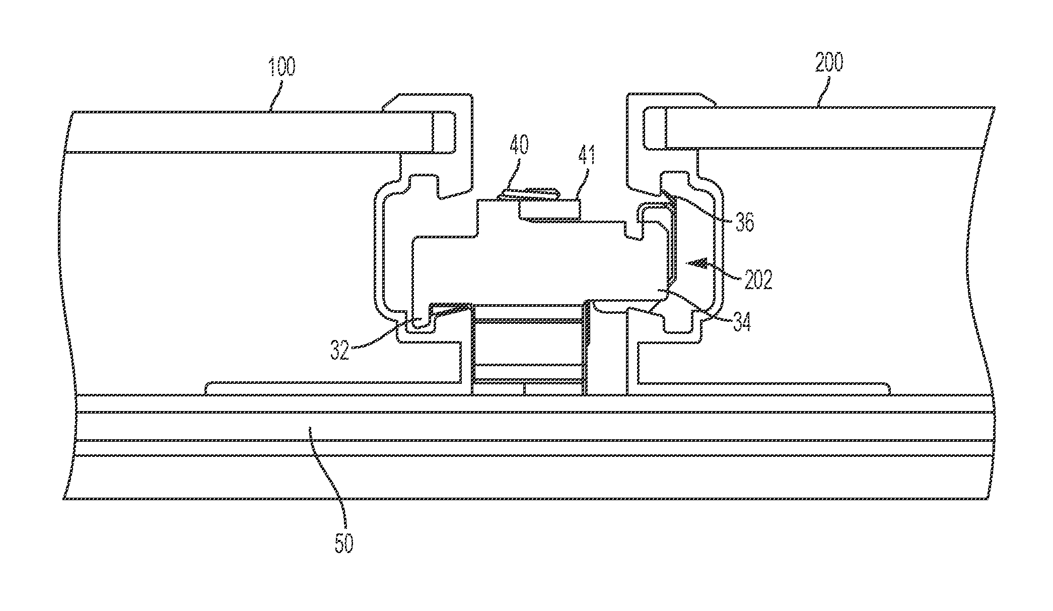
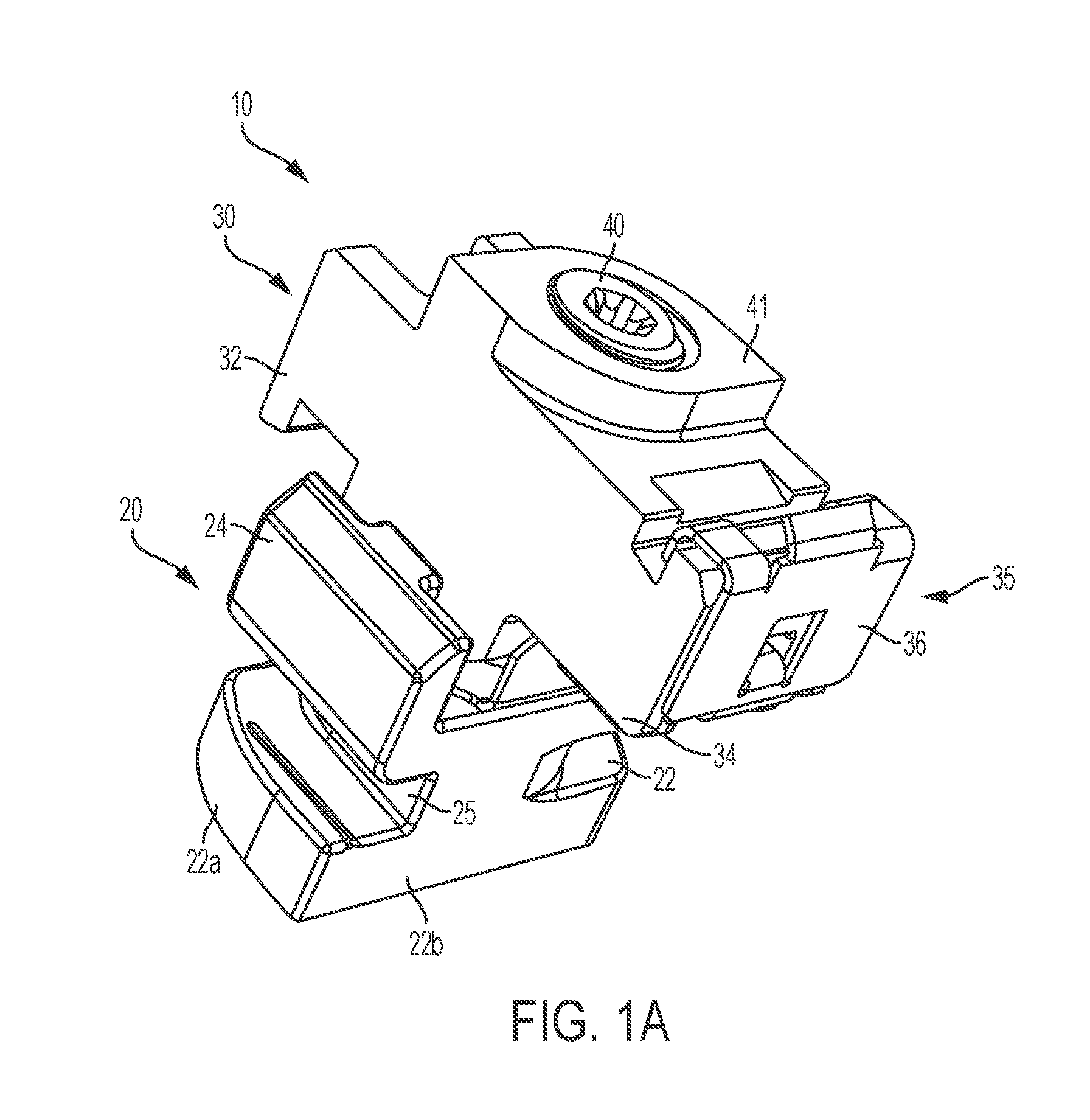
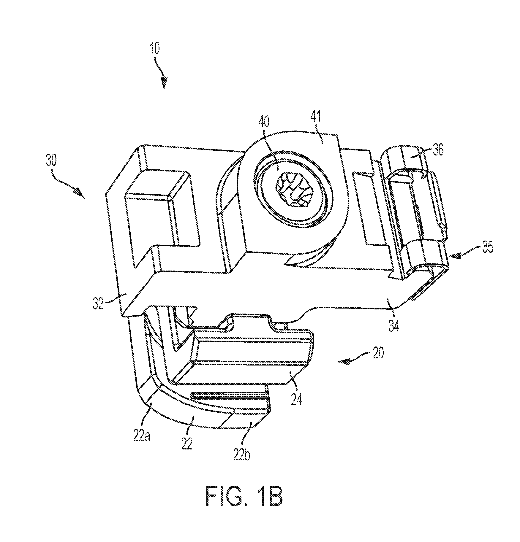
Photovoltaic mounting rail connector with drop-down connection to first photovoltaic module and slide-in connection to second photovoltaic module

a technology of photovoltaic modules and mounting rails, which is applied in the direction of connection contact members, coupling device connections, lighting and heating apparatus, etc., can solve the problems of photovoltaic modules, the installation techniques appropriate for roof structures built by relatively modern construction standards are not appropriate or safe for roof structures built according to relatively older or traditional construction standards, etc., to minimize the risk of damage to the second photovoltaic module, the effect of saving time and energy

Active Publication Date: 2017-03-02
TESLA INC
View PDF0 Cites 5 Cited by
  • Summary
  • Abstract
  • Description
  • Claims
  • Application Information

AI Technical Summary

Benefits of technology

The present system is a connector for attaching photovoltaic modules to a mounting rail, which allows for quick and easy installation. The connector can be easily attached onto one module and then a second module can be slid into position, without having to touch the connector. This eliminates the risk of damage to the second module and saves time and energy during the installation process. The system also includes a fastener that adjusts the distance between the upper and lower body portions of the connector to connect and pivot-connect the modules securely onto the rail. The minimal tooling required for installation makes the system easy to use. Overall, the present system provides a reliable and efficient solution for solar power generation.

Problems solved by technology

For some installations of solar panel arrays, the method of mounting and connecting photovoltaic modules can be restricted to an order of operations such that installation techniques appropriate for roof structures built by relatively modern construction standards are not appropriate or safe for roof structures built according to relatively older or traditional construction standards.

Method used


Image

  • Photovoltaic mounting rail connector with drop-down connection to first photovoltaic module and slide-in connection to second photovoltaic module
  • Photovoltaic mounting rail connector with drop-down connection to first photovoltaic module and slide-in connection to second photovoltaic module
  • Photovoltaic mounting rail connector with drop-down connection to first photovoltaic module and slide-in connection to second photovoltaic module

Examples


Embodiment Construction

[0020]Throughout this description for the purposes of explanation, numerous specific details are set forth in order to provide a thorough understanding of the many aspects and embodiments disclosed herein. It will be apparent, however, to one skilled in the art that the many aspects and embodiments may be practiced without some of these specific details. In other instances, known structures and devices are shown in diagram or schematic form to avoid obscuring the underlying principles of the described aspects and embodiments.

[0021]As used herein, certain terms identify the relative connections of structural element of the present system. In particular, the term “drop down” refers to a coupling of two structural elements where one structure clamps down on the other. Similarly, the term “slide-in” refers to a coupling of two structural elements where a first structure laterally moves into a receiving region of the second structure.

[0022]It can be understood that while the examples sho...


PUM


Abstract

A connector for attaching first and second photovoltaic modules to a mounting rail, with a lower body portion that rotates to lock into a mounting rail groove and an upper body portion with a hook that is lowered towards the lower body portion to grasp onto the first photovoltaic module and a key that receives the second photovoltaic module slidably-connected thereon.

Description

CROSS-REFERENCE TO RELATED APPLICATIONS[0001]This claims the benefit of priority to U.S. Provisional Application No. 62 / 211,330, titled “PHOTOVOLTAIC MOUNTING RAIL CONNECTOR WITH DROP-DOWN CONNECTION TO FIRST PHOTOVOLTAIC MODULE AND SLIDE-IN CONNECTION TO SECOND PHOTOVOLTAIC MODULE” and filed on Aug. 28, 2015, which is herein incorporated by reference in its entirety. This further incorporates by reference in their entireties U.S. patent application Ser. No. 14 / ______ (applicant ref. P168-2NUS) titled “SUPPORT SYSTEM FOR PHOTOVOLTAIC MOUNTING RAIL HAVING CYLINDRICAL BASE THAT ROTATES INTO A LOCKED POSITION” and U.S. patent application Ser. No. 14 / ______ (applicant ref P180-2NUS) titled “TILE AND SLATE ROOF FLASHING SYSTEMS”, both being filed concurrently on the same day as this application.TECHNICAL FIELD[0002]This relates to photovoltaic mounting systems, and to systems for securing photovoltaic modules onto mounting rails.BACKGROUND[0003]For some installations of solar panel array...

Claims


Application Information

Patent Timeline
Patent Type & Authority Applications(United States)
IPC IPC(8): H01R25/14H01R43/16H02S30/10H01R4/64
CPCH01R25/142H02S30/10H01R43/16H01R4/64F24S25/632F24S25/636F24S25/67F24S2025/014F24S2025/6002F24S2025/6004F24S2025/801F24S2025/807H02S20/10H02S30/00Y02E10/47Y02E10/50
Inventor HUDSON, TYRUSSEERY, MARTINBROUSSARD, RIVERKIMBERLEY, MALCOLM
Owner TESLA INC
Learn More