Injection molding system

a technology of injection molding and mold deformation, which is applied in the field of injection molding system, can solve the problems of not being able to detect abnormal conditions such as resin leakage and mold deformation, and not being able to correct detection,

Inactive Publication Date: 2017-03-09
FANUC LTD
View PDF4 Cites 2 Cited by
  • Summary
  • Abstract
  • Description
  • Claims
  • Application Information

AI Technical Summary

Benefits of technology

[0036]According to the present invention, an injection molding system capable of correctly controlling a nozzle touch force by

Problems solved by technology

Thus, the occurrence of abnormal conditions during molding such as resin leakage and deformation of a mold may not be detectable.
In the technology disclosed by JP 2013-56516 A, the proximity switch is installed in a position where the elastic member begins to contract and the proximity switch is incorporated into the nozzle touch mechanism unit

Method used


Image

  • Injection molding system
  • Injection molding system
  • Injection molding system

Examples


Embodiment Construction

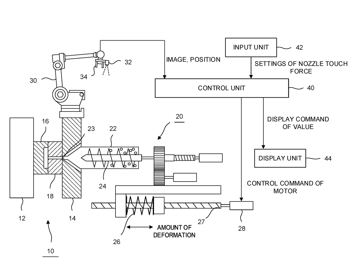
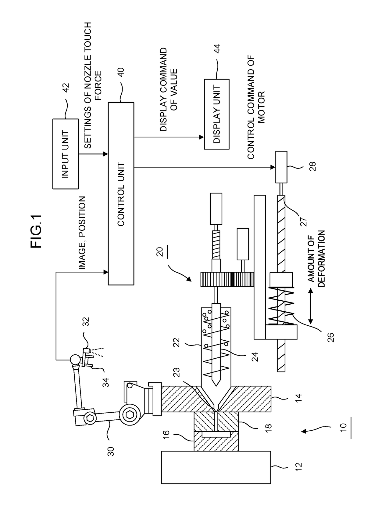
[0044]Hereinafter, the embodiment of the present invention will be described based on the drawings. FIG. 1 is a diagram showing an injection molding system according to the present embodiment. Reference numeral 10 is an injection molding machine and a movable platen 12 and a fixed platen 14 are provided in the injection molding machine 10. A movable side mold 16 is provided in the movable platen 12 and a fixed side mold 18 is provided in the fixed platen 14.

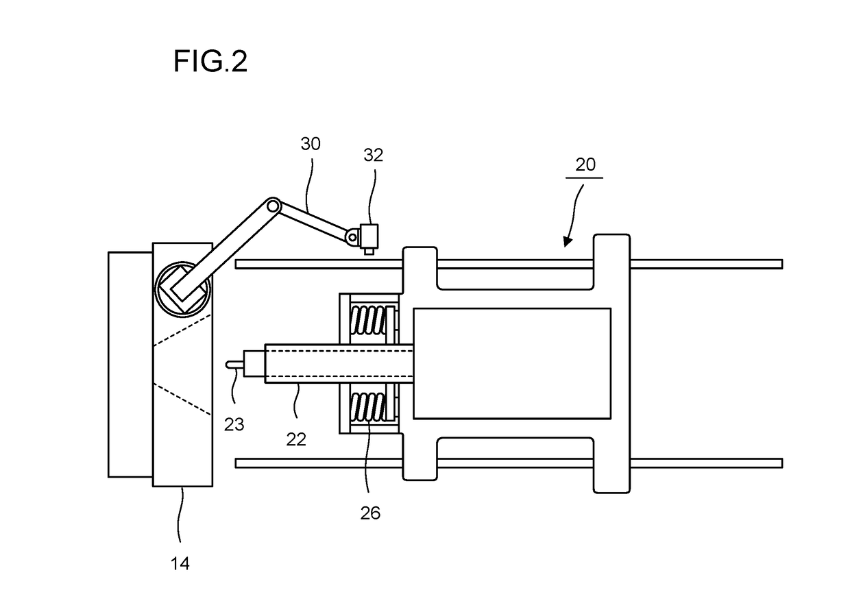
[0045]An injection cylinder 22, a nozzle 23 provided in a tip portion of the injection cylinder 22, and a screw 24 provided inside the injection cylinder 22 to stir and transfer resin are provided in an injection device 20. In addition, the amount of deformation of an elastic member 26 is changed by a ball screw 27 being rotated by driving of a motor 28. The position of the injection cylinder 22 is thereby changed and the relation of nozzle touch between the injection cylinder 22 and the fixed side mold 18 and a nozzle touch forc...


PUM

PropertyMeasurementUnit
Forceaaaaaaaaaa
Elasticityaaaaaaaaaa
Deformation enthalpyaaaaaaaaaa

Abstract

In an injection molding system, an amount of deformation of an elastic member is calculated from image data of the elastic member causing a nozzle to generate a nozzle touch force and a nozzle touch force of the nozzle is calculated by converting the amount of deformation. Accordingly, it becomes possible to detect abnormal conditions such as resin leakage and mold deformation and exercise correct control of the nozzle touch force.

Description

RELATED APPLICATIONS[0001]The present application claims priority to Japanese Patent Application Number 2015-175176, filed Sep. 4, 2015, the disclosure of which is hereby incorporated by reference herein in its entirety.BACKGROUND OF THE INVENTION[0002]1. Field of the Invention[0003]The present invention relates to an injection molding system, and in particular, relates to an injection molding system that moves forward an injection unit by a power unit such as a motor in an injection molding machine to generate a predetermined nozzle touch force.[0004]2. Description of the Related Art[0005]The injection molding machine includes a clamping unit and an injection unit. In a normal injection molding operation excluding when a resin is ejected, a nozzle of the injection unit abuts on a fixed side mold and a state in which a predetermined nozzle touch force is generated on the mold is maintained. If a continuous molding operation is performed while allowing the nozzle to be in contact wit...

Claims


Application Information

Patent Timeline
IPC IPC(8): B29C45/80B29C45/17
CPCB29C45/80B29C45/1774B29C2945/76695B29C2945/76505B29C2945/7618B29C2945/76083B29C45/1777B29C45/76
Inventor NAGANO, YASUMASASHIRAISHI, WATARU
Owner FANUC LTD
Why Eureka
Try Eureka