
Annular turbomachine combustion chamber

a combustion chamber and turbomachine technology, applied in the direction of machines/engines, mechanical equipment, light and heating equipment, etc., can solve the problems of inability to disassemble the first wall from the second wall, weaken the combustion chamber, and complicate the disassembly process, etc., to achieve the effect of convenient maintenance operation, easy disassembly and assembly, and fast and inexpensive assembly

Active Publication Date: 2017-03-09
SAFRAN HELICOPTER ENGINES
View PDF9 Cites 8 Cited by
  • Summary
  • Abstract
  • Description
  • Claims
  • Application Information

AI Technical Summary

Benefits of technology

The patent describes a new design for a combustion chamber that reduces the risk of cracks and leaks. This is achieved by using one or more pins that fit into a pair of holes, allowing the walls of the chamber to be assembled together without needing to weld or crimp them together. The pins can fit into the holes without any clearance, making them fit tightly together. This design also presents a small number of walls, making it easier and more cost-effective to assemble and maintain. Overall, this design reduces risks and improves the performance and reliability of combustion chambers.

Problems solved by technology

Assembling them together by welding makes it impossible to disassemble a first wall from a second wall, e.g. for maintenance or for the purpose of replacing one of the walls.
Assembly by bolting presents the drawback of encouraging cracks to appear in the vicinity of the holes in which the bolts are engaged because of the blocking that is generated, thereby weakening the combustion chamber.
In addition, assembling in those ways is complex, lengthy, and expensive.

Method used


Image

  • Annular turbomachine combustion chamber
  • Annular turbomachine combustion chamber
  • Annular turbomachine combustion chamber

Examples


Embodiment Construction

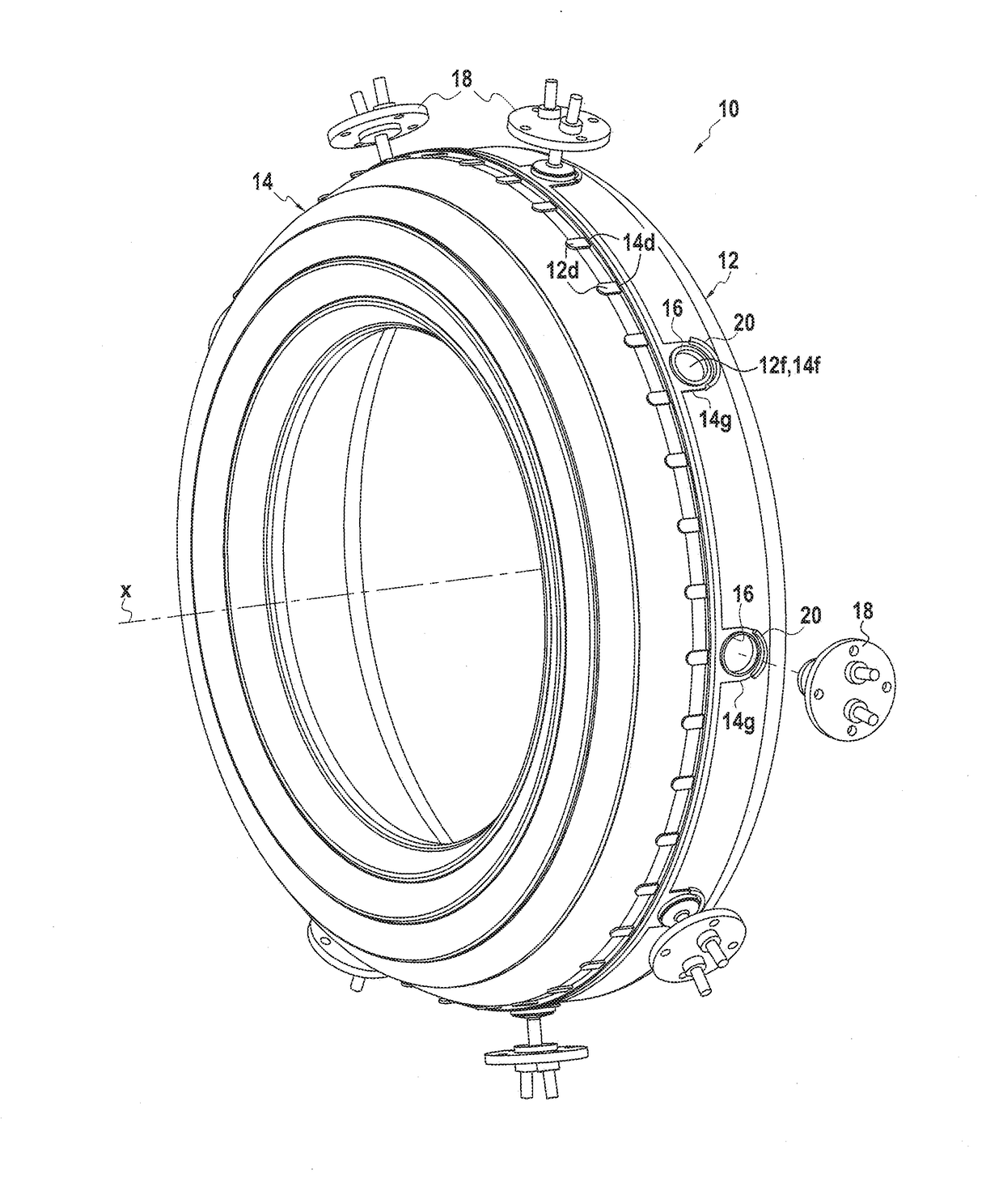
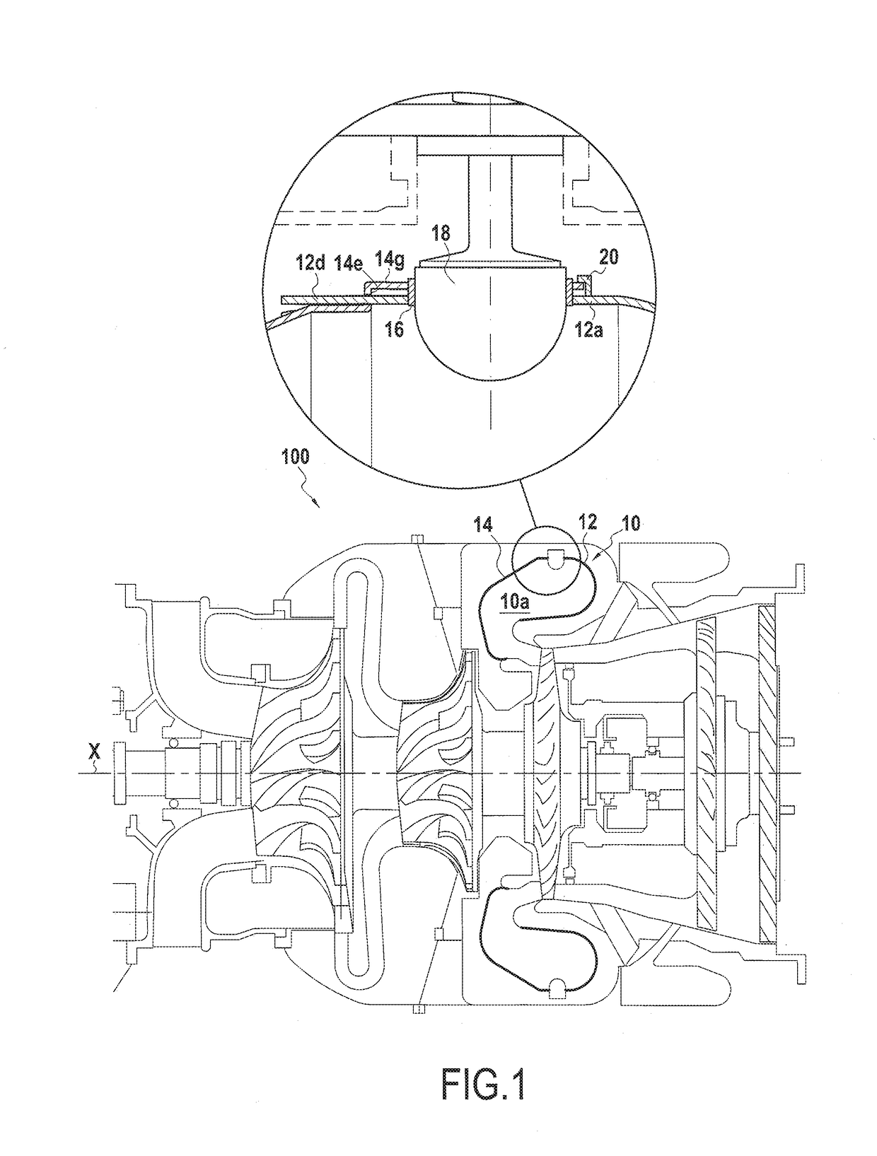
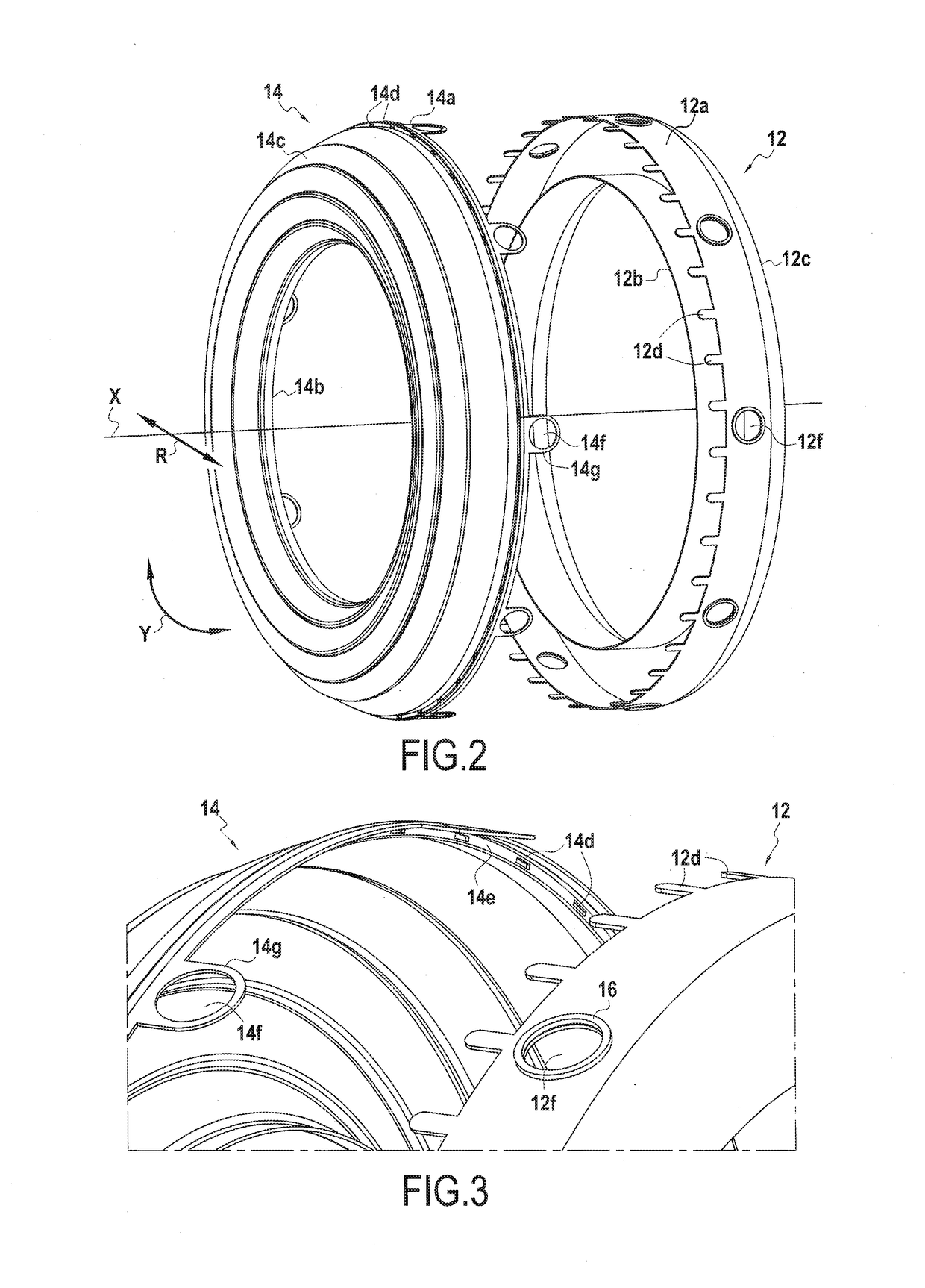
[0042]FIG. 1 shows a turbomachine 100 having an annular combustion chamber 10, while FIGS. 2 to 4 show the two annular walls 12 and 14 of the combustion chamber 10 in greater detail. It should be observed that the combustion chamber 10 is an annular chamber of the reverse flow type, but that the invention is not limited to this particular type of combustion chamber.

[0043]The combustion chamber 10 presents an axial direction (along the axis X), a radial direction R, and an azimuth direction Y. The combustion chamber 10 presents symmetry of revolution about the axis X. In this example, the first wall 12 forms a flame tube delimiting the volume in which the fuel ignites, i.e. where combustion takes place. The second wall 14 forms an outer bend and serves as a deflector for guiding the flow of gas coming from the flame tube. This combustion chamber example 10 has only two annular walls 12 and 14 for delimiting the volume 10a of the combustion chamber 10.

[0044]More particularly, each of ...


PUM


Abstract

An annular combustion chamber (10) for a turbomachine (100), the combustion chamber presenting an axial direction (X), a radial direction, and an azimuth direction, and comprising a first annular wall (12) and a second annular wall (14), each wall delimiting at least a portion of the volume of the annular combustion chamber (10), the first and second walls (12, 14) presenting complementary fitting elements (12d, 14d), the first wall (12) presenting at least one first through hole (12f), while the second wall (14) presents at least one second through hole (14f), the combustion chamber (10) also having at least one pin (18) engaged in a pair of holes comprising a first hole (12f) and a second hole (14f), said pin (18) locking the fitting of the first and second walls (12, 14).

Description

FIELD OF THE INVENTION[0001]The invention relates to the field of turbomachine combustion chambers, and more particularly to the field of annular combustion chambers for a turbomachine, and particularly but not exclusively for a helicopter turboshaft engine.[0002]The term “turbomachine” is used to mean any gas turbine apparatus that generates driving power, including in particular turbojets that provide thrust needed for propulsion in reaction to ejecting hot gas at high speed, and turboshaft engines where the driving power is delivered by rotating a drive shaft. For example, turboshaft engines are used as engines in helicopters, ships, trains, and indeed as industrial power plants. Turboprops (a turboshaft engine driving a propeller) are likewise turboshaft engines used as aeroengines.STATE OF THE PRIOR ART[0003]A conventional annular combustion chamber for a turbomachine presents an axial direction, a radial direction, and an azimuth direction, and it generally comprises five annu...

Claims


Application Information

Patent Timeline
IPC IPC(8): F23R3/52F23R3/28F23R3/00
CPCF23R3/52F23R3/28F23R3/002F23R3/60F05D2240/35F23R3/58F02C7/20F23D11/103F23R3/50F23R3/54F05D2230/64F23R3/283F23R3/42F23R2900/00017F05D2260/30F23R3/425F23R3/48F23R2900/00019F23C5/02F23R2900/00005F05D2230/51F23R3/46F05D2240/90F05D2230/50F23R2900/00018F05D2230/642F23R3/007F23R3/56
Inventor SAVARY, NICOLASBERTEAU, PATRICKCARRERE, BERNARDDUBOURDIEU, JEAN-MARCNAUDOT, LUDOVIC
Owner SAFRAN HELICOPTER ENGINES
Learn More