Method and device for detecting at least one sensor malfunction of at least one first sensor of at least one first vehicle

a technology of at least one sensor and a detection method, which is applied in the direction of external condition input parameters, instruments, transportation and packaging, etc., can solve problems such as incorrect conclusions, and achieve the effect of increasing the reliability of the signal detected by at least one sensor and increasing the safety of the user

Inactive Publication Date: 2017-03-09
ROBERT BOSCH GMBH
View PDF3 Cites 127 Cited by
  • Summary
  • Abstract
  • Description
  • Claims
  • Application Information

AI Technical Summary

Benefits of technology

[0007]The advantage of the present invention is that sensor malfunctions may also be detected if the sensor functions per se and a faulty signal is only detected due to certain circumstances, for example, induced by external conditions. In addition, both temporary malfunctions and permanent malfunctions may be detected by this method. Due to the comparison according to the present invention of the sensor signals of the sensors installed in different vehicles, in addition, a total of more than one individual sensor also participates in the detection of a signal, whereby the reliability that the signal is correctly detected by at least one sensor is increased. This plays a large role in the safety of a vehicle driven by a driver, but above all in the case of vehicles which drive in a partially or completely automated manner and in which the monitoring of the vehicles by sensors plays a necessary and also leading role.
[0008]The at least one first sensor of at least one first vehicle will preferably acquire an acquired variable, which is predefined according to acquisition criteria. The at least one sensor malfunction exists if the at least one first sensor of at least one first vehicle detects this detection variable according to predefined detection criteria incorrectly or not at all.
[0009]It may be an advantage of the present invention that the method may detect a malfunction both within the meaning of a false estimation and a total failure of a sensor. The false estimation is even detected if the sensor functions per se but, due to certain circumstances, for example, external conditions, still supplies a signal or also multiple signals with deficient accuracy or supplies a signal which results in an incorrect conclusion, for example, not recognizing an obstruction. The informative value of a signal recorded by a sensor, and the confidence, for example, of a user of the mobile unit, in the sensors of a vehicle may thus be generally increased.
[0010]In one particularly preferred specific embodiment, this at least one comparison variable is detected in the at least one first vehicle and / or in the at least one further second vehicle and / or outside the at least one first vehicle and outside the at least one further second vehicle in detection surroundings provided for this purpose. The latter alternative is also often referred to as a data cloud.
[0011]In addition, the at least one sensor malfunction is preferably displayed in the at least one first vehicle, and / or data values, which represent the at least one sensor malfunction, are stored in the at least one first vehicle and / or in the at least one further second vehicle and / or on at least one external storage medium, for example, in a so-called data cloud. In addition, the data values may be transmitted to at least one user of the at least one first vehicle and / or the at least one further second vehicle.
[0012]The advantages of these preferred specific embodiments result from the manifold potential uses which result from the information of the comparison variable. By way of the detection in the at least one first vehicle, the safety may be increased for the user of the at least one first vehicle and an instantaneous adaptation to safety-relevant conditions may be enabled, for example, the lack of recognition of hazards due to severe visibility restriction, induced by corresponding external conditions. Improvements with respect to the safety during automated driving, for example, also result due to the detection outside the at least one first vehicle.

Problems solved by technology

The false estimation is even detected if the sensor functions per se but, due to certain circumstances, for example, external conditions, still supplies a signal or also multiple signals with deficient accuracy or supplies a signal which results in an incorrect conclusion, for example, not recognizing an obstruction.

Method used


Image

  • Method and device for detecting at least one sensor malfunction of at least one first sensor of at least one first vehicle
  • Method and device for detecting at least one sensor malfunction of at least one first sensor of at least one first vehicle
  • Method and device for detecting at least one sensor malfunction of at least one first sensor of at least one first vehicle

Examples


Embodiment Construction

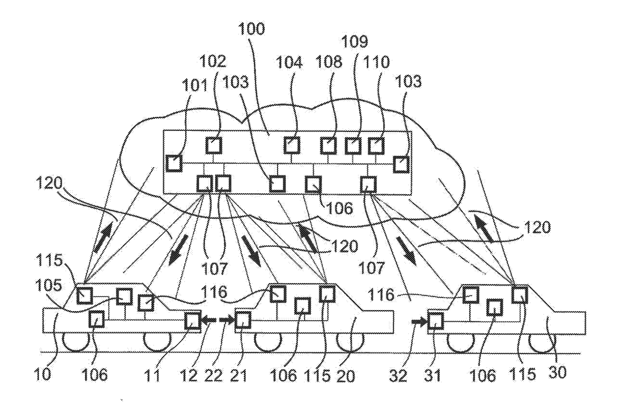
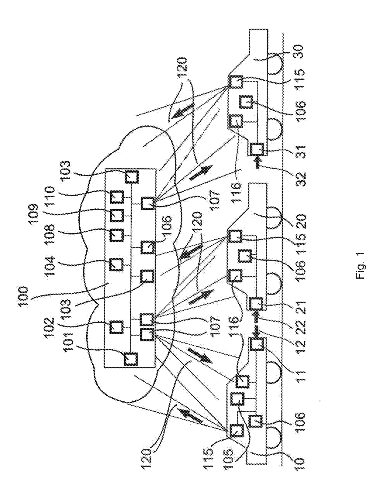
[0027]FIG. 1 shows an exemplary situation of the method according to the present invention for detecting at least one sensor malfunction of at least one first sensor 11 of at least one first vehicle 10. For illustration, in this specific embodiment, the method is shown, solely by way of example, on the basis of a sensor malfunction of a first sensor 11 of a first vehicle 10. The method is basically also suitable for detecting multiple sensor malfunctions of multiple sensors, which may be attached both to one and to multiple vehicles involved in the method.

[0028]In this exemplary embodiment, which is here solely by way of example, all vehicles 10, 20, 30 involved in the method are illustrated as four-wheeled vehicles. The method is expressly applicable for vehicles of all types, which includes both manned and unmanned vehicles, and also vehicles on land, water, or also in the air.

[0029]According to the present invention, a signal 12, shown as an arrow here, is detected by a first veh...


PUM


Abstract

A method and a device for detecting at least one sensor malfunction of at least one first sensor of at least one first vehicle, at least one first signal from the at least one first sensor of the at least one first vehicle being ascertained and this at least one first signal being compared according to predefined comparison criteria to at least one comparison variable, at least one further second signal from at least one second sensor of at least one further second vehicle being ascertained as this at least one comparison variable and the at least one sensor malfunction being detected in the at least one first vehicle as a function of the comparison.

Description

CROSS REFERENCE[0001]The present application claims the benefit under 35 U.S.C. §119 of German Patent Application No. DE 102015216494.2 filed on Aug. 28, 2015, which is expressly incorporated herein by reference in its entirety.FIELD[0002]The present invention relates to a method and a device for at least one vehicle for detecting at least one sensor malfunction of at least one sensor. To ascertain this at least one sensor malfunction, at least one further vehicle, also having at least one sensor, is regarded for comparison of the sensor values. After comparison of these sensor values, which takes place according to predefined comparison criteria, the sensor malfunction is determined and the piece of information about it is processed accordingly.BACKGROUND INFORMATION[0003]Conventional methods for detecting sensor malfunctions may be carried out both by direct readout of a control unit, and via data transmission in a repair shop. The sensor functions are checked in that signals are ...

Claims


Application Information

Patent Timeline
Patent Type & Authority Applications(United States)
IPC IPC(8): G01D18/00G07C5/00G07C5/08
CPCG01D18/00G07C5/008G07C5/0816B60R16/02G01D21/00G07C5/0808G01R31/007B60W2050/0215B60W2556/55B60W2556/65B60W2555/20B60W2556/45B60W50/0205
Inventor SKUPIN, CHRISTIANLANGENBERG, MARKUSZAUM, DANIELHOMANN, HANNOKNORR, MORITZ MICHAELKLEJNOWSKI, LUKASGERALDY, ALEXANDERPAGEL, MICHAELCAKAR, EMREMARX, JOCHENHINTERLEITNER, ISABELLAMIELENZ, HOLGER
Owner ROBERT BOSCH GMBH
Why Eureka
Try Eureka