Rotating Swivel Assemblies for Outriggers

Active Publication Date: 2017-03-16
TACO METALS LLC
View PDF75 Cites 11 Cited by
  • Summary
  • Abstract
  • Description
  • Claims
  • Application Information

AI Technical Summary

Benefits of technology

[0009]It is accordingly an object of the invention to provide an outrigger assembly having a rotating line guide which overcomes the above-mentioned disadvantages of the heretofore-known devices and methods of this general type and whi

Problems solved by technology

This further increases the number of fish

Method used


Image

  • Rotating Swivel Assemblies for Outriggers
  • Rotating Swivel Assemblies for Outriggers
  • Rotating Swivel Assemblies for Outriggers

Examples


Example

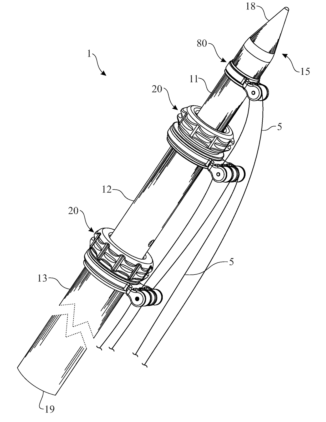
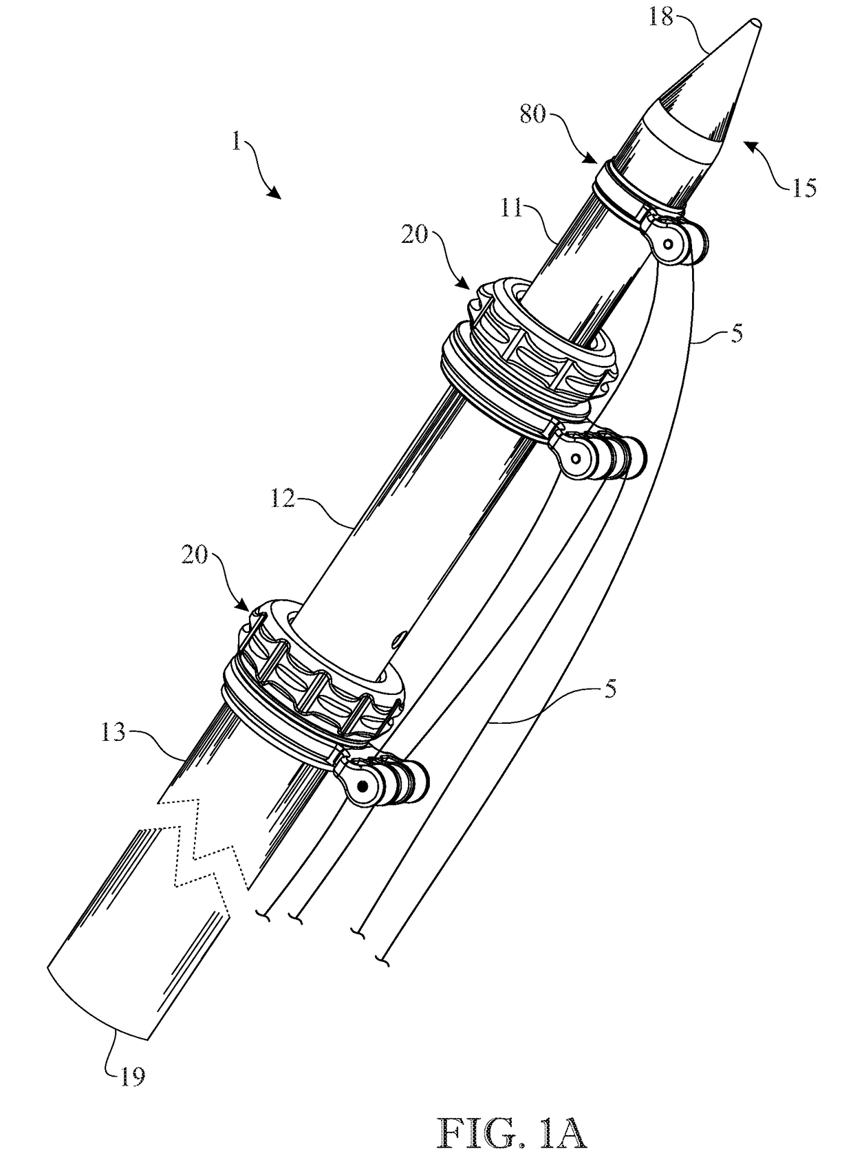
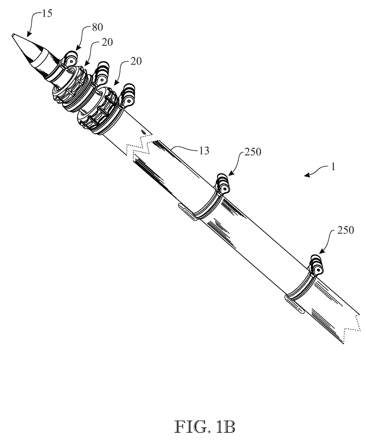
[0037]Referring now to the figures of the drawing in detail and first, particularly to FIG. 1A and 1B which show an outrigger assembly 1, having three telescoping tubes, which include an outer tube 13 with a center tube 12 longitudinally displaceable therein and an inner tube 11 longitudinally displaceable within the center tube 12. Respective outrigger tube bearings 22 are disposed between the inner tube 11 and the center tube 12 and between the center tube 12 and the outer tube 13. As shown in FIG. 2, the outrigger tube bearings 22 provide the guidance for the telescoping extension of the tubes 11 and 12. The inner tube 11 has an outrigger tip 18 at a free end 15 and outer tube 13 has a base end / outrigger butt 19 of the outrigger assembly 1, which is disposed in an outrigger mount on a fishing vessel.

[0038]Rigging line guide assemblies 20 are shown at the junctions between the respective tubes 11, 12, and 13. An exploded view of a line guide assembly is shown in FIG. 3. The outrig...


PUM


Abstract

An outrigger assembly includes an outrigger tube with a longitudinal axis. A swivel ring is disposed on the outrigger tube. The swivel ring is rotatable with respect to the outrigger tube about the longitudinal axis. The swivel ring has a line guide for guiding an outrigger rigging line in a direction along the longitudinal axis.

Description

CROSS REFERENCE TO RELATED APPLICATIONS[0001]This application claims benefit of U.S. Provisional Patent Application No. 62 / 218,607 filed Sep. 15, 2016, entitled Roller Outrigger, the disclosure of which is incorporated herein by reference in its entirety.BACKGROUND OF THE INVENTION[0002]a) Field of the Invention[0003]The invention relates to rigging line guides and roller assemblies on an outrigger pole or tube used for fishing and trolling from fishing vessels, the outrigger tube being a single tube or series of telescoping tubes that support a fishing line to allow boats to trawl more than one fishing line in the water without tangling, having a wider spread of trolling lures and to simulate a school of fish.[0004]b) Description of the Related Art[0005]It is well known to use outrigger poles or tubes in fishing vessels. Outrigger tubes are a long tube or a series of tubes, one within another, for extending or telescoping the outrigger tube, both referred to herein as an outrigger ...

Claims


Application Information

Patent Timeline
IPC IPC(8): A01K91/08B63B35/14
CPCB63B35/14A01K91/08B63B35/16
Inventor SEROCKI, PHILIP J.
Owner TACO METALS LLC
Why Eureka
Try Eureka