
Sole of shoe having partially adjustable height depending on inclination

a technology of inclination and shoe sole, which is applied in the field of shoe sole, can solve the problems of inconvenient feeling of the wearer, and achieve the effects of increasing the height of the fluid casing at low position, and increasing the heigh

Inactive Publication Date: 2017-03-16
KIM YONG SOO
View PDF12 Cites 18 Cited by
  • Summary
  • Abstract
  • Description
  • Claims
  • Application Information

AI Technical Summary

Benefits of technology

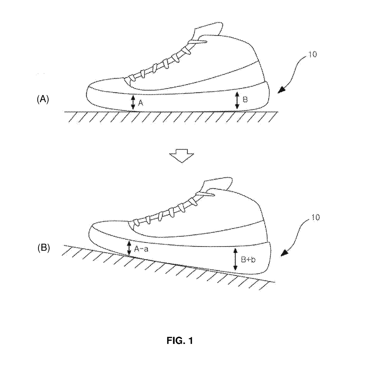
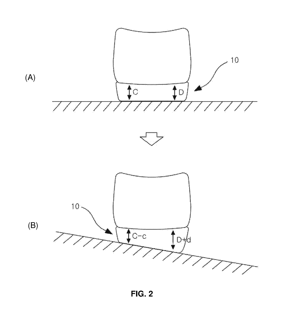
The present invention provides a shoe sole that can make a person feel more comfortable when walking on a slope. This is achieved by correcting the angle of inclination so that it is close to horizontal, which improves safety and reduces physical exhaustion. The invention is particularly useful for golf shoes and hiking boots.

Problems solved by technology

If a person who wears shoes walks in an inclined plane in the front and rear or left and right direction, he or she may inevitably feel inconvenient due to the slope itself although the shoes have any cushion function.

Method used


Image

  • Sole of shoe having partially adjustable height depending on inclination
  • Sole of shoe having partially adjustable height depending on inclination
  • Sole of shoe having partially adjustable height depending on inclination

Examples


first embodiment

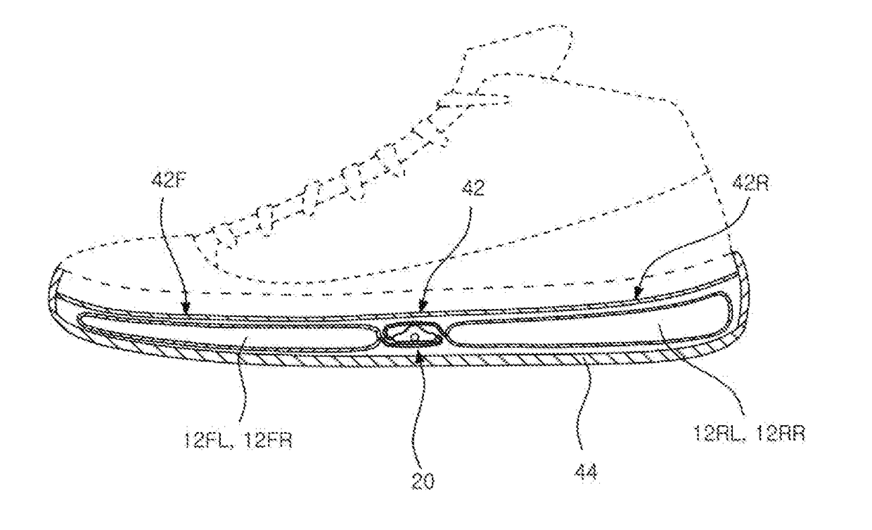
[0046]In accordance with the present invention of FIG. 6, the check ball 28 may be made of a material having greater specific gravity than the fluid in the valve body, and the connecting passages 26a and 26b formed on both inner sides of the valve body 22 are connected to the fluid casings 12 placed in opposite directions. That is to say, the connecting passage 26a connects the left side (front portion in the sole) of valve body to fluid casing 12RL which is in right side (rear portion in the sole). And the connecting passage 26b connects the right side (rear portion in the sole) of valve body to fluid casing 12FL which is in left side (front portion in the sole).

[0047]In this case, the fact that check ball 28 may be made of a material having greater specific gravity than the fluid means that, for example, the fluid may be made of gas, such as air, and the check ball 28 may be made of a metallic material having sufficient strength. In case that the fluid is a liquid, and the check b...

second embodiment

[0079]Furthermore, in the aforementioned embodiment, the fluid within the fluid casing 12 has been illustrated as being gas and the check ball 28 has been illustrated as being made of a metallic material having greater specific gravity and thus has a setting force. the present invention shown in FIGS. 10 and 11 may be said to be an embodiment in which the fluid within the fluid casings 12A and 12B is a liquid and the check ball 28 is made of a material that has smaller specific gravity than the liquid and thus has buoyancy, that is, a material having smaller specific gravity than that of fluid.

[0080]In the second embodiment, when a wearer walks in an inclined plane, the slope of the sole can be adjusted only when the fluid casing placed at a low position becomes high. Accordingly, as shown in FIGS. 10 and 11, a first fluid casing 12A and a second fluid casing 12B are connected by a valve unit 20 so that a fluid can move within the first fluid casing 12A and the second fluid casing 1...


PUM


Abstract

A shoe sole includes a sole contact portion 42, a ground contact portion 44, a plurality of fluid casings 12 configured to include a pair of fluid casings arranged in the front and rear direction and a pair of fluid casings arranged in the left and right direction between the sole contact portion and the ground contact portion and made of an elastic material, and plurality of valve units 20 and 30 configured to connect the pair of fluid casings in the front and rear direction and the pair of fluid casings in the left and right direction and to permit a flow of a fluid only from fluid casings at a high position to fluid casings at a low position when the sole of the shoe is inclined in the front and rear direction and / or in the left and right direction.

Description

REFERENCE TO RELATED APPLICATIONS[0001]This application claims the priority benefit of Korean Patent Application No. 10-2015-0130834 filed on Sep. 16, 2015, the entire contents of which are incorporated herein by reference.FIELD OF THE INVENTION[0002]The present invention relates to the sole of the shoe and, more particularly to the sole of the shoe, which is configured to have a sense of balance by adjusting the height of a fluid casing embedded in the sole, with respect to the inclination of ground in the left and right or front and rear direction.BACKGROUND OF THE INVENTION[0003]In general, a variety of types of shoes, such as hiking boots and golf shoes, in addition to common walking boots frequently worn in daily life are produced and come into the market. In such shoes, one of the most important functions may be said to be comfortable feeling in the feet when walking. Such comfortable feeling of the feet may be said to be based on cushioning.[0004]In order to provide comfortab...

Claims


Application Information

Patent Timeline
Patent Type & Authority Applications(United States)
IPC IPC(8): A43B13/18A43B13/20
CPCA43B13/181A43B13/20A43B13/189A43B13/148A43B13/203A43B13/186F16K15/048F16K15/04A43C15/09
Inventor KIM, YONG SOO
Owner KIM YONG SOO
Learn More