
Method for making a cementitious mortar based composite panel with light translucency properties and a structure of light translucent material

a technology of cementitious mortar and composite panels, which is applied in the manufacture of cementitious articles, can solve the problems of difficult positioning of optical fibers in the block, affecting the quality of cementitious mortar, and reducing the translucency effect, so as to achieve cost-effective and easy-to-use effects, light translucency properties, and avoid processing and material was

Inactive Publication Date: 2017-03-16
ITALCEMENTI
View PDF0 Cites 1 Cited by
  • Summary
  • Abstract
  • Description
  • Claims
  • Application Information

AI Technical Summary

Benefits of technology

This patent is about a new method for making cementitious mortar based composite panels with light translucency properties. The method simplifies the assembly process, reduces material waste, and avoids optical drawbacks. The use of a monolithic structure made of light translucent plastic material, obtained by plastic injection molding, reduces manufacturing costs and allows for panels of different sizes. The modular design allows for the positioning of all the translucent material elements needed to make the panel in the formwork, further reducing manufacturing costs. The use of modular structures also allows for automation and reduces the need for specialized personnel.

Problems solved by technology

However, such a technology has proven to be rather ineffective because the translucency effect, i.e. the transmission of light from one side of the panel to the other, is conditioned by the light intensity incident on the block and of its incidence angle.
It has been seen that beyond a given value of such an angle, the translucency effect gradually decreases, this constituting an obvious limitation of such a technique.
Other drawbacks related to this technology are found, for example, in the difficult positioning of the optical fibers in the block and the need for complicated steps of cutting and polishing to finish off the article.
This obviously implies waste of material, particularly if large parts are required.
However, it has been observed that the methods for making panels with PMMA elements currently have huge drawbacks which require a solution in order to make this technology easily useable.
The second aspect relates to the cost of the cutting process used to configure such elements.
This is a further criticality in terms of manufacturing costs.
A further drawback of “optical” nature has arisen in the use of the panels made with “chain-like” elements caused by the joint regions between the “through portions” and the lower height portion of the elements themselves.
Indeed, it has been found that in the manufacturing process described above, panels are often obtained in which the chains are arranged “irregularly” because parallelism is poor and straightness lacks.
This firstly compromises the good appearance results of the panels themselves and thus the final quality of the product.

Method used


Image

  • Method for making a cementitious mortar based composite panel with light translucency properties and a structure of light translucent material
  • Method for making a cementitious mortar based composite panel with light translucency properties and a structure of light translucent material
  • Method for making a cementitious mortar based composite panel with light translucency properties and a structure of light translucent material

Examples


Embodiment Construction

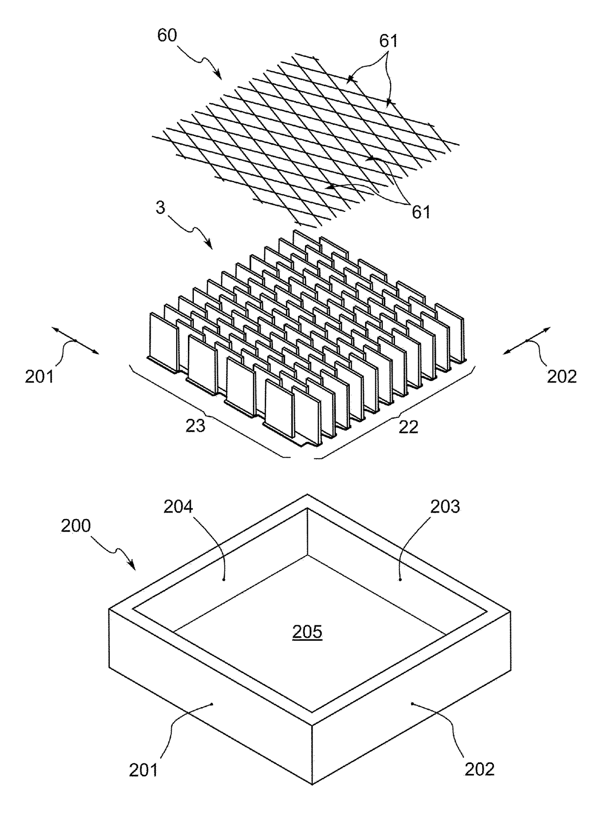
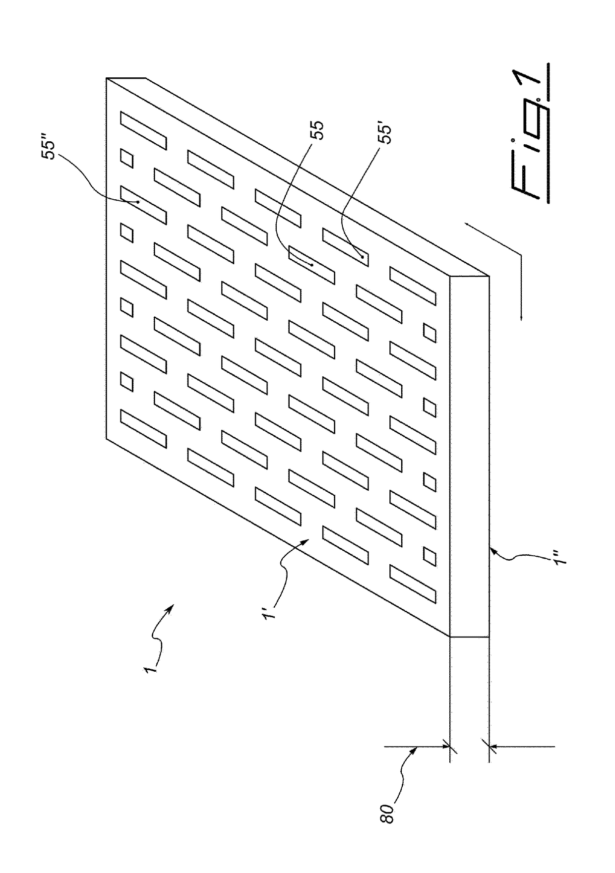
[0025]The present invention thus relates to a method for making a cementitious mortar based composite panel comprising a plurality of elements 55, 55′, 55″ made of light translucent material which allows the light transmission through the panel 1 from one first flat side 1′ to a second flat side 1″ of the panel itself. FIG. 1 is a perspective view of a panel 1 which can be made according to the present invention in which the flat sides 1′,1″, which are the main sides of the panel 1, i.e. those with a greater extension, are indicated. For the purposes of the invention, the distance between the first side 1′ and the second side 1″ defines the thickness of the panel 1 (indicated by reference numeral 80), such a distance being evaluated according to a direction substantially orthogonal to parallel planes on which the two main sides 1′,1″ are developed.

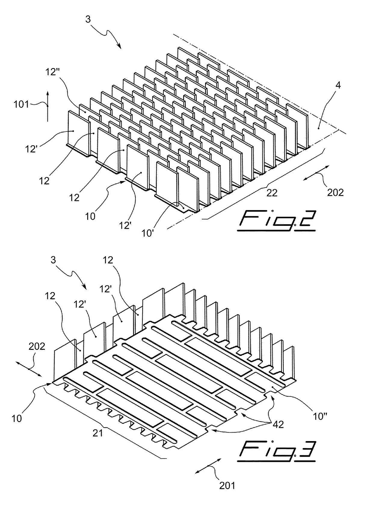
[0026]The method according to the present invention includes making a monolithic structure 3 of light translucent material adapted to be ...


PUM

PropertyMeasurementUnit
light transmissionaaaaaaaaaa
light translucentaaaaaaaaaa
translucentaaaaaaaaaa

Abstract

The present invention relates to a method for making a cementitious mortar based composite panel comprising portions made of translucent material which are developed from a first side (1′) of the panel (1) to a second side (1″) opposite to the first side. The method includes making a monolithic structure (3) made of light translucent material provided with a base (10) and a plurality of elements (12,12′,12″) which develop from said base (10). The structure is made by means of a plastic injection molding process. The method includes arranging such a structure inside a formwork so as to arrange all the elements in the predetermined position for the subsequent step of pouring in a single operation. The method finally includes finishing off the cementitious mortar obtained following the hardening of the cementitious mortar, by eliminating said base (10) of said structure (3) and by defining said flat sides (1′,1″) of said panel (1).

Description

FIELD OF THE INVENTION[0001]The present invention relates to the manufacturing of cementitious articles, in particular of cementitious mortar based composite panels with light translucency properties. In particular, the present invention relates to a new method for making a cementitious mortar based composite panel. The present invention also relates to a composite panel comprising such a structure and to a monolithic structure made of translucent material which can be used in the aforesaid method.PRIOR ART[0002]The use of cementitious articles with light translucency properties is known. As known, a possible manufacturing process of such cementitious articles (e.g. described in patent application WO03097954) includes the use of optical fibers inside the articles which are then finished off into blocks or panels. However, such a technology has proven to be rather ineffective because the translucency effect, i.e. the transmission of light from one side of the panel to the other, is c...

Claims


Application Information

Patent Timeline
Patent Type & Authority Applications(United States)
IPC IPC(8): B28B23/00E04C2/04E04C2/54
CPCB28B23/0037E04C2/044E04C2/54E04C2/04
Inventor CARMINATI, ARONNERIZZO, NICOLA
Owner ITALCEMENTI
Learn More