Working method for end portion of plate member, manufacturing method for plate member, working apparatus for end portion of plate member, and plate member

a technology for working methods and plate parts, which is applied in the field of working methods manufacturing methods for plate parts, and working apparatuses for end portions of plate parts. it can solve the problems of not being able to accommodate the entire cut surface inside the plate member, and the beauty of the plate member is not enhanced as expected, so as to enhance the plate member of the invention, improve the beauty, and facilitate and reliably manufacture the pla

Inactive Publication Date: 2019-02-19
MITSUIYA INDS +1
View PDF11 Cites 0 Cited by
  • Summary
  • Abstract
  • Description
  • Claims
  • Application Information

AI Technical Summary

Benefits of technology

[0014]According to the above configuration, with the first step and the second step, the outer peripheral end of the thin portion (in other words, an end portion including a cut surface of the plate member) is moved toward the main body portion of the plate member. After theses steps, the cut surface of the plate member does not exist at a terminal portion (an outer edge portion) of the plate member. Further, with the third step, the outer peripheral end of the thin portion (the end portion including the cut surface of the plate member) is moved further inward than the surface of the main body portion in the thickness direction (in other words, so as not to be exposed to the outside of the plate member). Accordingly, even when part of the outer peripheral end of the thin portion is exposed on the surface of the plate member due to the above various variations (variations in working accuracy in the first step and the second step and variations in the dimensions of the plate member), the outer peripheral end including the exposed portion is buried in the plate member in the third step. In addition, in general, the movement of the outer peripheral end of the thin portion in the thickness direction does not require a complicated method, and hence it is possible to easily execute the third step. Therefore, with the above configuration, the outer peripheral end of the thin portion is prevented from being exposed on the surface of the plate member easily and reliably.
[0101]As has been described thus far, “the working method for the end portion of the plate member” of the invention achieves an effect of being able to prevent the end portion (the cut surface) of the resin plate member from being exposed on the surface of the resin plate member as easily and reliably as possible. In addition, “the manufacturing method for the plate member” of the invention achieves an effect of being able to easily and reliably manufacture the plate member in which the beauty is improved and the sense of harm is reduced by properly working the end portion. Further, “the working apparatus for the end portion of the plate member” of the invention achieves an effect of being able to easily and reliably implement an improvement in the beauty of the plate member and a reduction in the sense of harm by properly working the end portion of the plate member. In addition, “the plate member” of the invention achieves an effect that the beauty is excellent and the sense of harm is small.

Problems solved by technology

However, in general, there are cases where the entire portion of the cut surface is not necessarily accommodated inside the plate member due to variations in working accuracy when the end portion of the plate member is worked (e.g., at the time of heating and pressing or folding) and variations in the dimensions of the plate member, and part of the cut surface is exposed on a surface of the plate member.
In these cases, there is a possibility that the beauty of the plate member is not enhanced as expected.

Method used


Image

  • Working method for end portion of plate member, manufacturing method for plate member, working apparatus for end portion of plate member, and plate member
  • Working method for end portion of plate member, manufacturing method for plate member, working apparatus for end portion of plate member, and plate member
  • Working method for end portion of plate member, manufacturing method for plate member, working apparatus for end portion of plate member, and plate member

Examples


first embodiment

[0120]First, a first embodiment of the invention will be described.

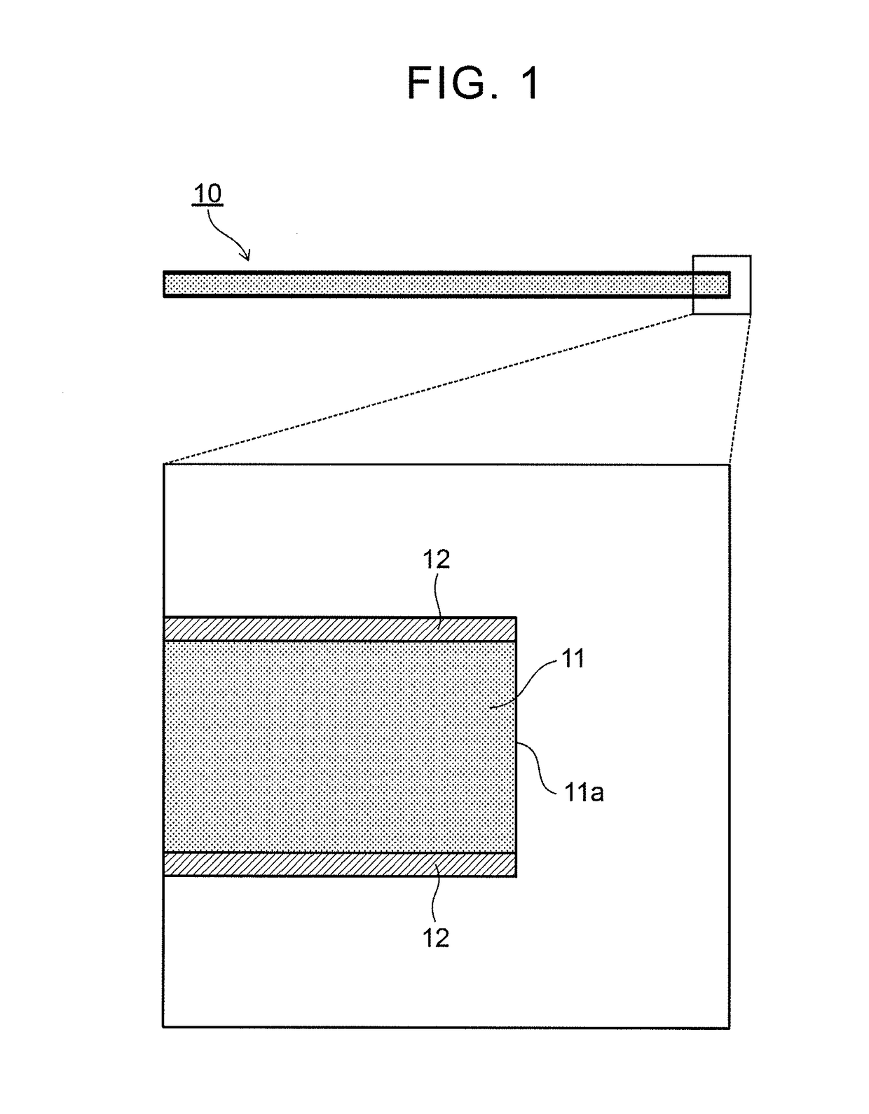
[0121]FIG. 1 shows a schematic configuration of a plate member (a plate member before being worked) to which a working method (a first working method) according to the embodiment is applied. As shown in FIG. 1, a plate member 10 includes a plate-shaped body 11, and buffer layers 12 provided on surfaces (two main surfaces) of the plate-shaped body 11. The plate-shaped body 11 is formed of a thermoplastic resin, and the buffer layer 12 is formed of a nonwoven fabric. An end surface 11a of the plate-shaped body 11 is a cut surface formed when the plate member 10 is worked into a shape suitable for its use.

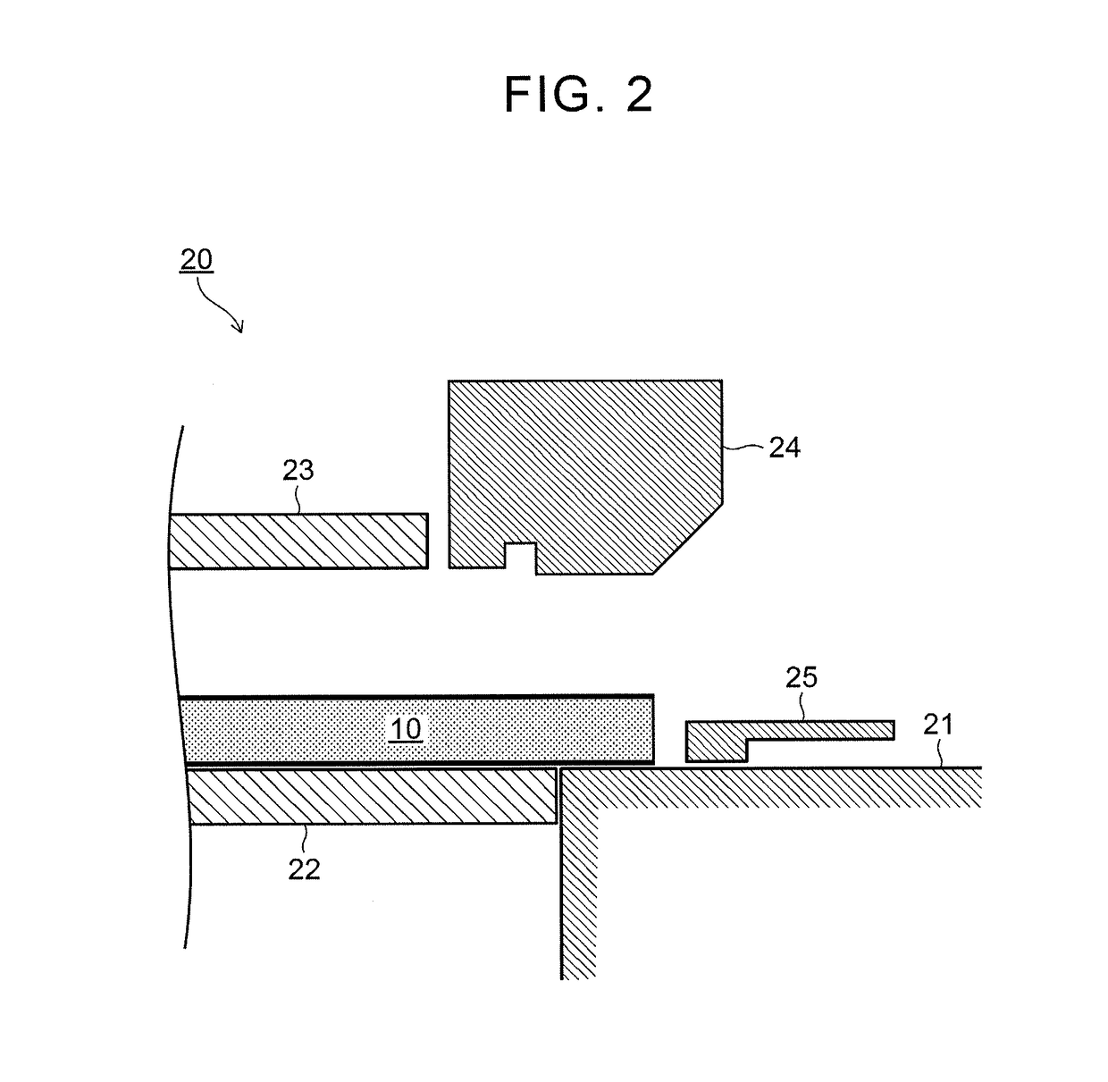
[0122]FIG. 2 shows a schematic configuration of a working apparatus 20 (a first working apparatus. Hereinafter referred to as “an apparatus 20”.) according to the embodiment. As shown in FIG. 2, the apparatus 20 includes a stationary lower pad 21, a movable lower pad 22, a movable upper pad 23, a heated blade 24, and a...

second embodiment

[0144]Next, a second embodiment of the invention will be described.

[0145]Main differences between the second embodiment and the first embodiment are (1) the entire portion of the thin portion including the outer peripheral end of the thin portion is pressed, and (2) the slide cam is fixed so as not to be movable and the thin portion is pressed against the slide cam in the procedure for pressing the outer peripheral end of the folded thin portion (the procedure 6 described above).

[0146]Hereinbelow, procedures for performing a working method (a second working method) according to the embodiment on the plate member will be described with reference to FIGS. 9 to 15 with the above differences being described mainly. In other words, based on FIGS. 9 to 15, a manufacturing method (a second manufacturing method) of the plate member of the embodiment, a working apparatus (a second working apparatus) of the end portion of the plate member according to the embodiment, and, by extension, a plat...


PUM

PropertyMeasurementUnit
thicknessaaaaaaaaaa
shapeaaaaaaaaaa
radius of curvatureaaaaaaaaaa

Abstract

A working method for an end portion of a plate member includes heating and pressing the end portion of the plate member formed of a thermoplastic resin in a thickness direction to form a thin portion, folding the thin portion such that a pressed surface is positioned inside to move an outer peripheral end of the thin portion as an end portion on an outer peripheral side of the plate member to the vicinity of a main body portion of the plate member to which an inner end of the thin portion as an end portion on an inner side of the plate member is connected, and pressing the outer peripheral end of the thin portion in the thickness direction to move the outer peripheral end thereof further inward than a surface of the main body portion in the thickness direction.

Description

TECHNICAL FIELD[0001]The invention relates to a working method for an end portion of a plate member formed of a thermoplastic resin (e.g., resin cardboard or the like. Hereinafter, the plate member is also referred to as “a resin plate member” for the convenience of description), a manufacturing method for the resin plate member, a working apparatus for the end portion of the resin plate member, and the resin plate member.BACKGROUND ART[0002]Conventionally, a resin plate member is put to various uses (e.g., a floor material of a trunk of an automobile or the like). In general, the resin plate member is cut into a desired shape corresponding to its use, and is then subject to a step of performing various working processes on its end portion (terminal portion) including a cut surface from the viewpoint of improving beauty of the resin plate member and reducing a sense of harm, whereby the resin plate member is manufactured.[0003]For example, in one of conventional working methods (her...

Claims


Application Information

Patent Timeline
Patent Type & Authority Patents(United States)
IPC IPC(8): B29C53/04B29C69/00B29C67/00B29K101/12B29K105/00
CPCB29C67/0044B29C69/001B29K2105/256B29K2101/12B29C53/04
Inventor HASEGAWA, SATOSHIMINOURA, WATARUONO, TAKUJINISHI, SACHIKO
Owner MITSUIYA INDS
Why Eureka
Try Eureka