
Automatically determining sensor location in a virtualized computing environment

a virtual computing environment and automatic determination technology, applied in data switching networks, high-level techniques, instruments, etc., can solve the problems of manual drive, time-consuming processes, and process errors

Active Publication Date: 2017-03-16
CISCO TECH INC
View PDF7 Cites 30 Cited by
  • Summary
  • Abstract
  • Description
  • Claims
  • Application Information

AI Technical Summary

Benefits of technology

The present disclosure relates to determining the location of sensors in a virtualized network system without the need for additional configuration. The technical effect of the patent text is to provide a method for automatically determining the location of sensors in a large scale virtualized computing environment, based upon information collected from packets and traffic flows observed by the sensors. This is useful for applications that need to know where the sensor is located, such as network diagnostics and security-related operations. The method does not require any special form or type of sensor observation, and can be performed without additional configuration.

Problems solved by technology

However, use of a configuration file to determine the location of a sensor requires updating the configuration file each time that a new sensor is deployed or when an existing sensor migrates to a new location.
However, both of these approaches are manually driven and time-consuming processes.
In addition, these processes are also error prone, especially when a virtual machine containing a sensor is moved to a different machine (or different hypervisor).

Method used


Image

  • Automatically determining sensor location in a virtualized computing environment
  • Automatically determining sensor location in a virtualized computing environment
  • Automatically determining sensor location in a virtualized computing environment

Examples


example embodiments

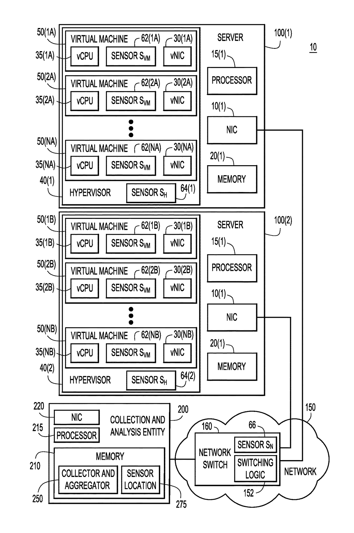
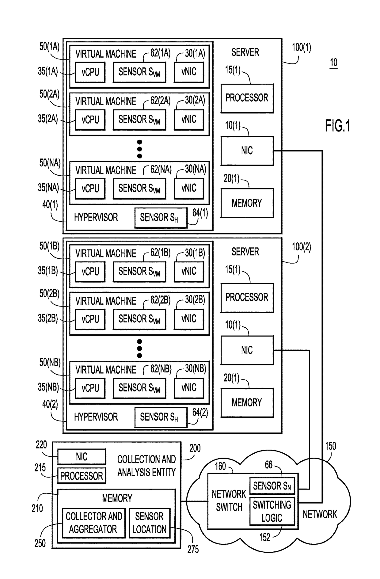
[0014]Presented herein are techniques for automatically determining the location of sensors deployed in a large scale virtualized computing environment, based upon information collected from packets and / or traffic flows (including control flows), observed by the sensors. The packets of traffic that are observed for purposes of the techniques presented herein do not need to be of any special form or type.

[0015]Virtualization enables improved efficiency with regard to utilization of computing resources. For example, computing resources of a physical server may be distributed among a plurality of virtual machines with the same or different operating systems. Virtual machines may be instantiated, migrated, or removed in response to changing computing demands.

[0016]In a datacenter or other large computing deployment, there may be millions of live sensors distributed throughout the network, reporting information associated with traffic flows / packets, e.g., as part of control flows, to a c...


PUM


Abstract

Methods, systems, and computer readable media are provided for determining, in a virtualized network system, a relationship of a sensor relative to other sensors. In a virtualized computing system in which a plurality of software sensors are deployed and in which there are one or more traffic flows, captured network data is received from the plurality of sensors, the captured network data from a given sensor of the plurality of sensors indicating one or more traffic flows detected by the given sensor. The received captured network data is analyzed to identify, for each respective sensor, a first group of sensors, a second group of sensors, and a third group of sensors, wherein all traffic flows observed by the first group of sensors are also observed by the second group of sensors, and all traffic flows observed by the second group of sensors are also observed by the third group of sensors. For each respective sensor, a location of each respective sensor relative to other sensors within the virtualized computing system is determined based upon whether the respective sensor belongs to the first group of sensors, the second group of sensors, or the third group of sensors.

Description

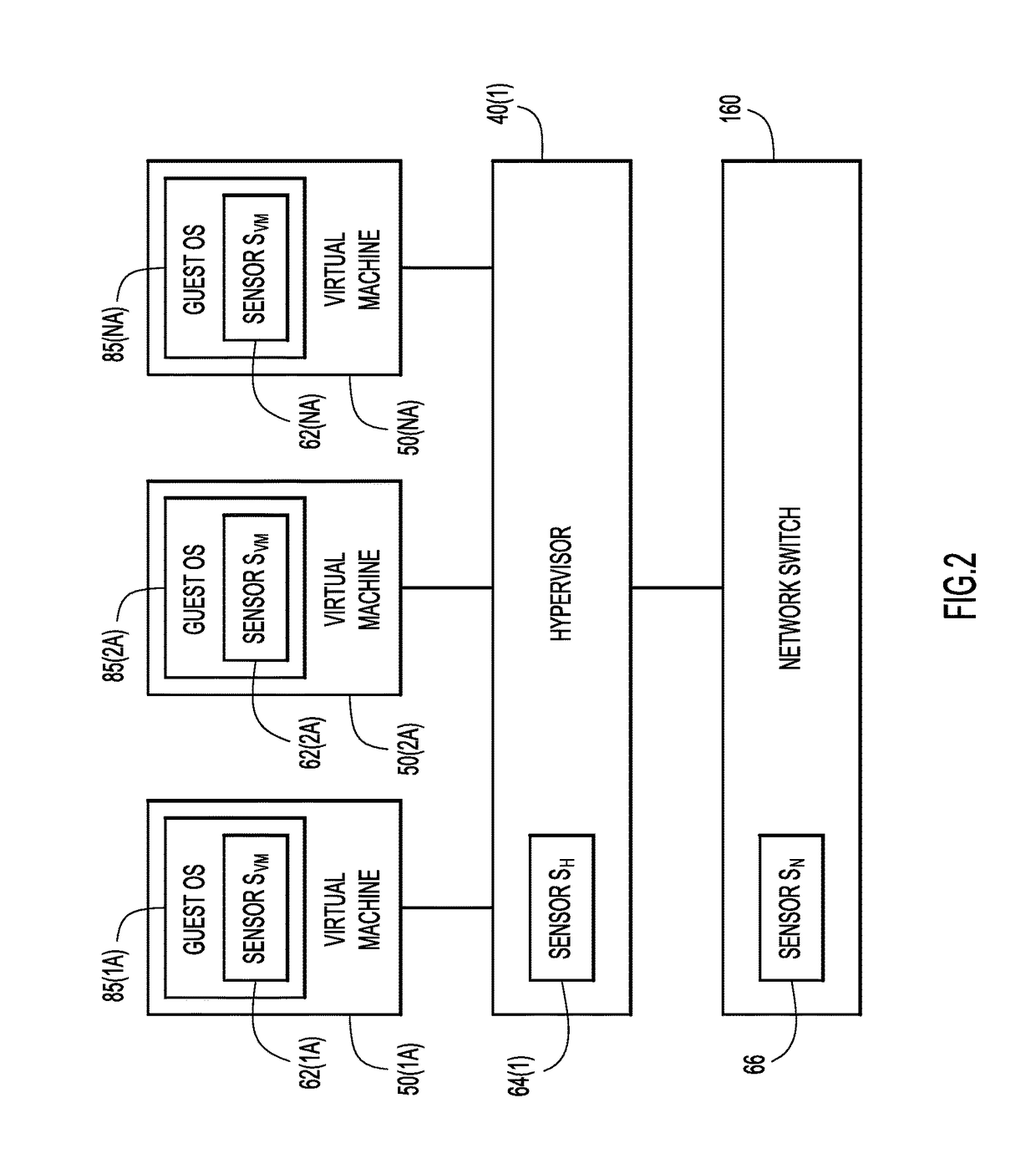
TECHNICAL FIELD[0001]The present disclosure relates to determining the location of sensors in a network, and in particular, to determining the location of sensors relative to other sensors as well as the environment in which the sensors are located, without additional configuration of the system.BACKGROUND[0002]A software sensor can be deployed on a virtual machine, on a hypervisor managing a plurality of virtual machines, or within a physical switch (e.g., a switching Application Specific Integrated Circuit (ASIC) or a router).[0003]The sensor reads a configuration file, e.g., a file manually created and updated by an administrator, in order to determine the location at which the sensor has been deployed, e.g., whether the sensor is located on a virtual machine, a hypervisor, or a physical switch, and also, to determine the hypervisor (or physical machine's name and Internet Protocol (IP) address) in case the sensor is located inside a virtual machine. However, use of a configurati...

Claims


Application Information

Patent Timeline
Patent Type & Authority Applications(United States)
IPC IPC(8): G06F9/455H04L12/26
CPCG06F9/45558H04L43/12G06F2009/4557G06F2009/45595G06F2009/45591H04L43/026Y02D30/50H04L41/0893H04L41/12
Inventor PRASAD, ROHIT C.GANDHAM, SHASHIDHAR R.YADAV, NAVINDRADEEN, KHAWARCHANG, SHIH-CHUNKULSHRESHTHA, ASHUTOSHGUPTA, ANUBHAV
Owner CISCO TECH INC
Learn More