Connector assembly having cpa

Inactive Publication Date: 2017-03-16
MOLEX INC
View PDF11 Cites 13 Cited by
  • Summary
  • Abstract
  • Description
  • Claims
  • Application Information

AI Technical Summary

Benefits of technology

[0017]First, this disclosure enables a CPA insertion force to be maintained such that when the connector position assurance (CPA) part has been fastened and prior to the fastening of the counterpart connector, it is able to withstand a force of at least 8.0 kgf, by preventing vertical slippage due to the formation of an edge on the front of the locking lever of the CPA part.
[0018]Second, this disclosure enables increased CPA fastening force and removal force by inserting the CPA part fr

Problems solved by technology

Accordingly, in the prior art, because it has not been possible to achieve the required CPA insertion force of 8.0 kgf or greater prior to fastening the counterpart connector, product reliability has been poor.
In additi

Method used


Image

  • Connector assembly having cpa
  • Connector assembly having cpa
  • Connector assembly having cpa

Examples


Example

[0029]Hereinbelow, a preferred embodiment of the connector assembly of this disclosure for use in an electronic device will be described, with reference to the attached drawings. Please note that in describing this disclosure, the detailed explanation is omitted of functions and components which are common knowledge and would unnecessarily obscure the substance of the disclosure.

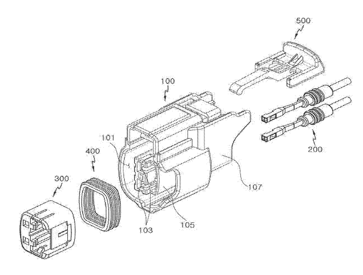
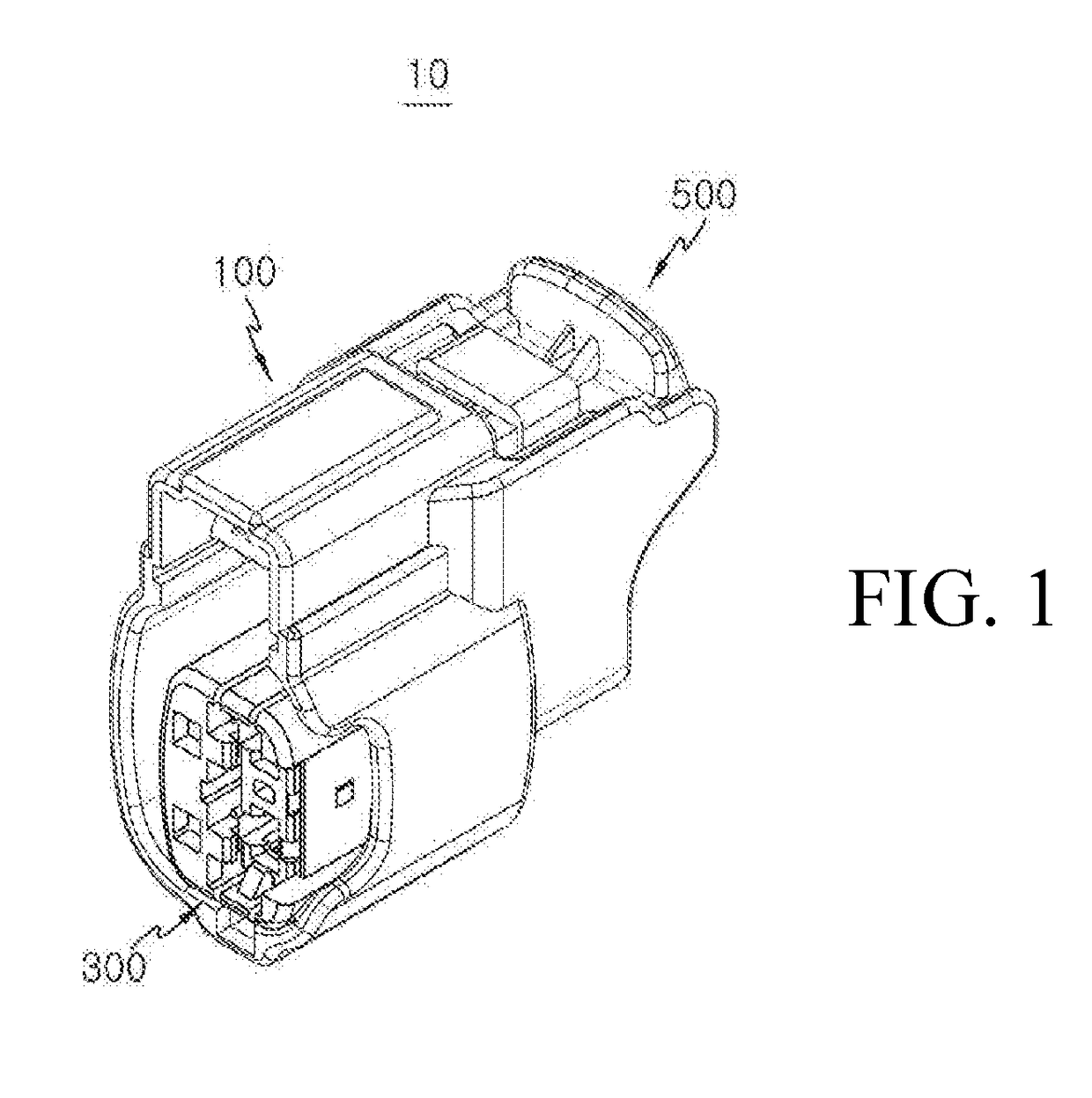
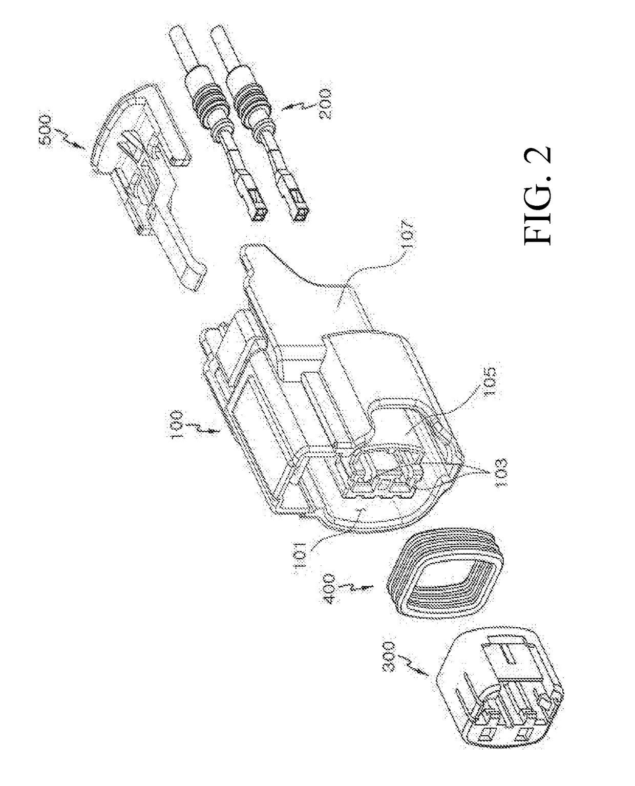
[0030]FIG. 1 is a perspective view of a connector assembly according to one embodiment of this disclosure; FIG. 2 is an exploded perspective view of FIG. 1; FIG. 3 is a rear perspective view of the connector housing; FIG. 4 is a view of the connector housing from the rear.

[0031]As shown in FIGS. 1 through 4, the connector assembly 10 according to an embodiment of this disclosure may comprise a housing 100, connector terminal 200, terminal position assurance part 300, sealing part 400, and connector position assurance part 500.

[0032]In the connector housing 100, an opening 101 is formed at the front to enable...


PUM


Abstract

A connector assembly is provided which has a connector position assurance apparatus that maintains a required CPA insertion force when the CPA is fastened and before the counterpart connector is fastened.

Description

RELATED APPLICATIONS[0001]This application claims priority to Korean Application No. 10-2015-0130943, filed Sep. 16, 2015, which is incorporated herein by reference in its entirety.TECHNICAL FIELD[0002]This disclosure relates to a connector, and more specifically to a connector assembly having a connector position assurance apparatus.BACKGROUND ART[0003]Generally, in electronic devices, electrical connectors are furnished for purposes of electrical contact. In addition, a connector position assurance (CPA) apparatus is typically installed to ensure that the connector is in locking position when a counterpart connector is inserted.[0004]For example, the ignition coil connector that supplies electricity to the ignition coil of an automobile has a CPA mounted on one side of the connector housing, and the counterpart connector may be inserted into the forward opening of the connector housing so as to be locked in place. This CPA is required to satisfy a CPA insertion force of at least 8...

Claims


Application Information

Patent Timeline
IPC IPC(8): H01R13/627
CPCH01R13/6272H01R13/639
Inventor KIM, JOON WOO
Owner MOLEX INC
Why Eureka
Try Eureka