Conversion of Clarifier to Suction Pipe System

a technology of suction pipe and clarifier, which is applied in the direction of sedimentation settling tank feed/discharge, separation process, sedimentation settling tank, etc., can solve the problems of disruptive and expensive conversion

Active Publication Date: 2017-03-23
OVIVO INC
View PDF9 Cites 1 Cited by
  • Summary
  • Abstract
  • Description
  • Claims
  • Application Information

AI Technical Summary

Benefits of technology

[0007]With the invention the suction duct/suction pipe clarifier conversion is made much more efficiently, with no need to penetrate existing concrete. A new sludge discharge vertical downpipe is provided in a center column/influent column, with a 90° elbow fixed to the bottom end of this pipe before reaching the tank floor. The elbow opening is oriented horizontally, and this is welded to a hole formed in the wall of the center column being installed, so that the RAS vertical discharge pipe is sealed to the column at that opening

Problems solved by technology

This conversion is disruptive and expensive.
Many treatment plants have been hesitant to

Method used


Image

  • Conversion of Clarifier to Suction Pipe System
  • Conversion of Clarifier to Suction Pipe System
  • Conversion of Clarifier to Suction Pipe System

Examples


Embodiment Construction

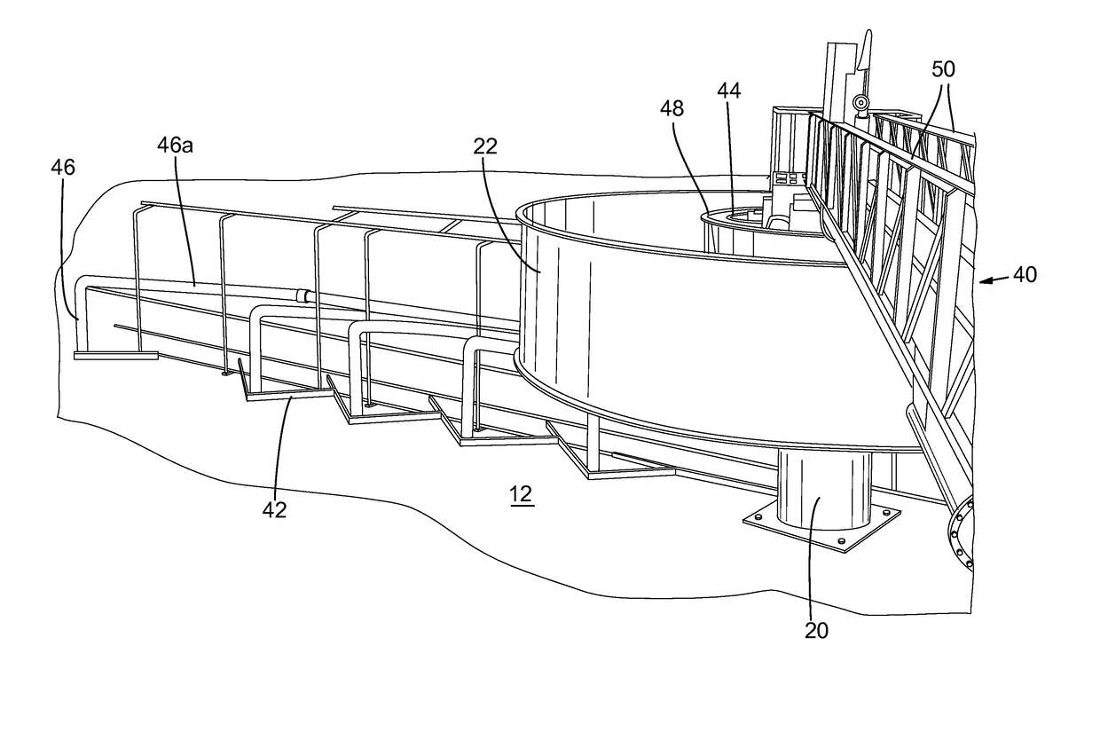
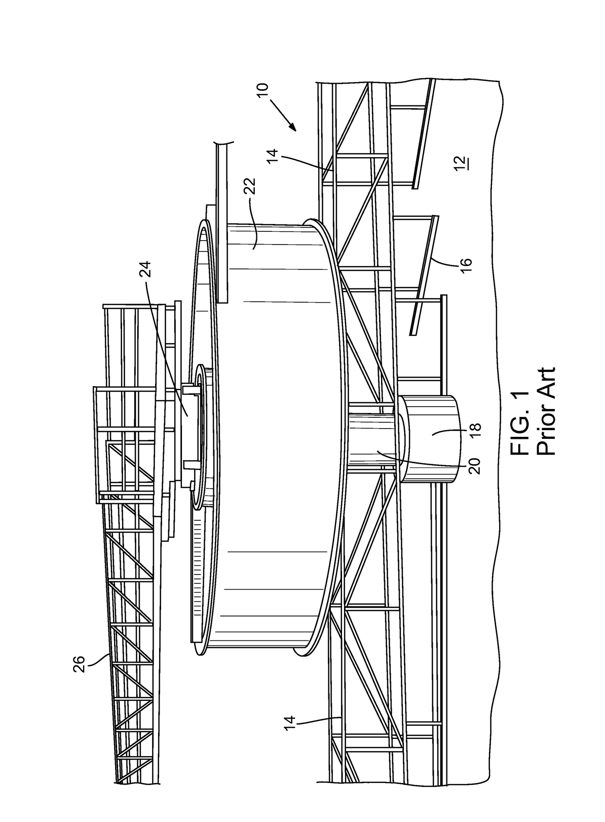
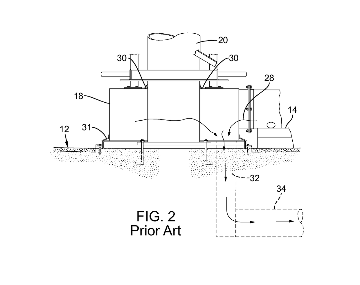
[0019]FIG. 1 is a perspective view showing, in part, a suction duct clarifier system 10 of the prior art, of the type which can be converted to a suction pipe clarifier system according to the invention. The drawing shows a clarifier basin floor 12, rake arms 14 that rotate and include rakes 16 that rake sludge along the basin floor, a sludge collection manifold and drum 18 at the base of a center column 20, the drum 18 being rotatable along with the rake arms, a large feedwell 22 above the rake arms (rotatable or stationary), and a drive unit 24 at the top of the center column, for rotating the movable components. A foot bridge is also indicated at 26, for access to the drive unit and other central components for maintenance. Below the rakes 14 is a sludge suction duct (not shown) that conveys the raked sludge to the sludge collection drum 18, where the sludge collects to be discharged out through a discharge port in the floor. The collection drum 18 is rotatable and has seals enga...


PUM


Abstract

In a wastewater treatment system, a suction duct clarifier is converted to a suction pipe clarifier without penetrating existing concrete at the base of the tank. An elevated sludge collection box is added, positioned on the center column to rotate with rake arms, and a series of sludge riser pipes extend from the rake arms up into the sludge collection box for sludge delivery by hydraulic pressure differential. A sludge discharge downpipe is provided within the center/influent column for delivery of sludge from the collection box, and at the bottom of this pipe, above the tank floor, the discharge pipe exits through an opening in the center/influent column. At the outside of this opening is a sludge transfer box that receives sludge exiting the discharge pipe and conveys it down through the existing floor opening and to the existing under-floor RAS return pipe.

Description

BACKGROUND OF THE INVENTION[0001]This invention is concerned with wastewater treatment systems. In particular, the invention encompasses a conversion of a suction duct clarifier to a suction pipe clarifier in an efficient manner without the need for penetrating the floor of the clarifier tank.[0002]Suction duct clarifiers do not elevate sludge collected by the rake arms, but instead include horizontal pipes that convey raked sludge into a center sludge collection drum that surrounds the center influent column, is sealed against the column and rotates along with the rake arms. A floor opening is located within the annular space emcompassed by the drum, and this provides a vertical duct for movement of the sludge from the drum down below the floor to a horizontal RAS return pipe that conveys the sludge out of the clarifier. This pipe is under suction, so that suction exists in the sludge collection drum and draws the sludge to that drum from suction ducts supported by the rake arms.[0...

Claims


Application Information

Patent Timeline
IPC IPC(8): C02F11/12B01D21/06B01D21/24B01D21/00
CPCC02F11/12B01D21/0003C02F2201/004B01D21/245B01D21/06B01D21/0006B01D21/34B01D21/2427
Inventor HEIMDAL, TORVORWALLER, JOHN
Owner OVIVO INC
Why Eureka
Try Eureka