A resonant dc-dc power converter assembly

Active Publication Date: 2017-03-23
DANMARKS TEKNISKE UNIV
View PDF4 Cites 36 Cited by
  • Summary
  • Abstract
  • Description
  • Claims
  • Application Information

AI Technical Summary

Benefits of technology

[0009]The skilled person will understand that the first and second inductors in one set of embodiments are configured for magnetically coupling the first and second resonant DC-DC power converters to each other by forcing substantially 0 degree phase shift between corresponding resonant voltage waveforms of the first and second resonant DC-DC power converters. These 0 degree phase shift, or “in-phase”, embodiments of the present resonant DC-DC power converter assembly are useful because the magnetic coupling between the first and second resonant DC-DC power converters forces their switching frequencies to be substantially identical and locked to each other, i.e. forcing synchronous operation of the first and second resonant DC-DC power converters. The synchronous operation enforced by the magnetic coupling between the first and second inductors eliminates or at least attenuates sum and difference switching frequency components otherwise inherently generated by small phase and switching frequency differences or offsets between a pair of nominal identical, but unlocked or asynchronous, resonant DC-DC power converters. The sum and difference switching frequency components lead to undesirable EMI emissions at frequencies far away from the nominal switching frequencies of the first and second resonant DC-DC power converters. These inherent phase offsets and switching frequency offsets are caused by manufacturing tolerances between nominally identical active and passive components of the first and second resonant DC-DC power converters, aging effects, temperature drift etc. Furthermore, the first and second resonant DC-DC power converters of the “in-phase” embodiments of the resonant DC-DC power converter assembly are capable of sharing a single rectification circuit, and optionally a resonant inductor, leading to a lower component count, smaller size and lower manufacturing c

Problems solved by technology

The sum and difference switching frequency components lead to undesirable EMI emissions at frequencies far away from the nominal switching frequencies of the first and second resonant DC-DC power converters.
This feature leads to significant decrease of ripple voltage levels on the DC power su

Method used


Image

  • A resonant dc-dc power converter assembly
  • A resonant dc-dc power converter assembly
  • A resonant dc-dc power converter assembly

Examples


first embodiment

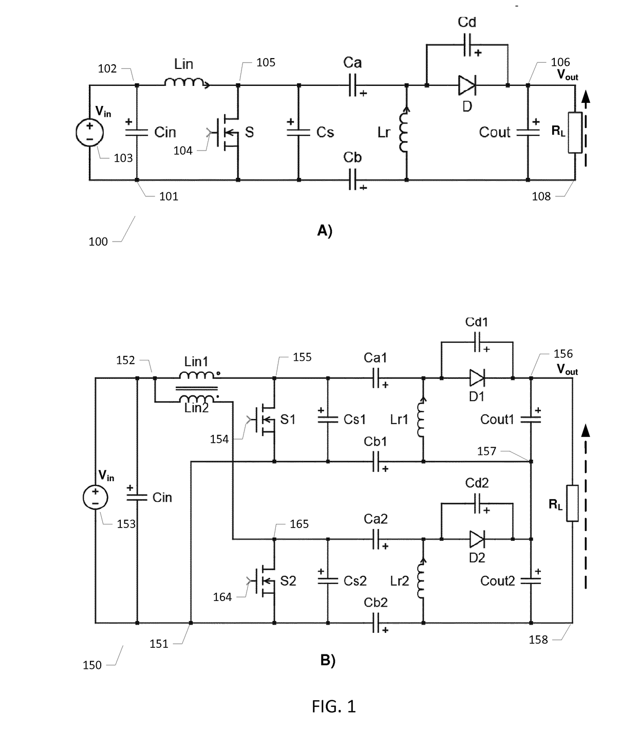
[0047]FIG. 1B) is a simplified electrical circuit diagram of a resonant DC-DC power converter assembly 150 in accordance with the invention comprising a pair of magnetically coupled isolated SEPIC DC-DC power converters. The resonant DC-DC power converter assembly 150 comprises a first isolated SEPIC converter built around semiconductor switch S1 and a second isolated SEPIC converter built around semiconductor switch S2. The first and second SEPIC DC-DC power converters are interconnected, or mutually coupled, via first and second magnetically coupled input inductors Lin1 and Lin2. Lin1 and Lin2 are arranged or configured to force substantially 180 degrees phase shift between resonant voltage waveform at the outputs, i.e. drain voltages in the present embodiment, of the first and second semiconductor switches S1, S2. The open dot symbol at the input inductor Lin1 and the closed dot symbol at the input inductor Lin2 indicate that the windings of these inductors are arranged to produc...

second embodiment

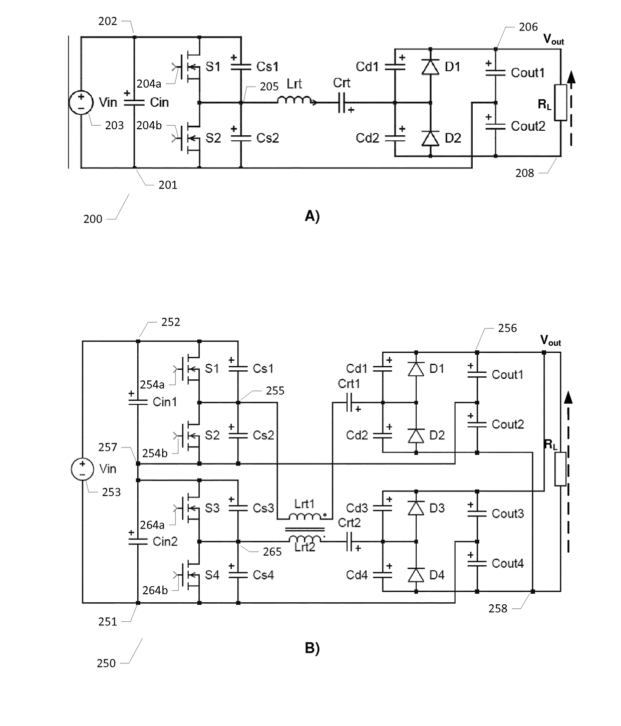
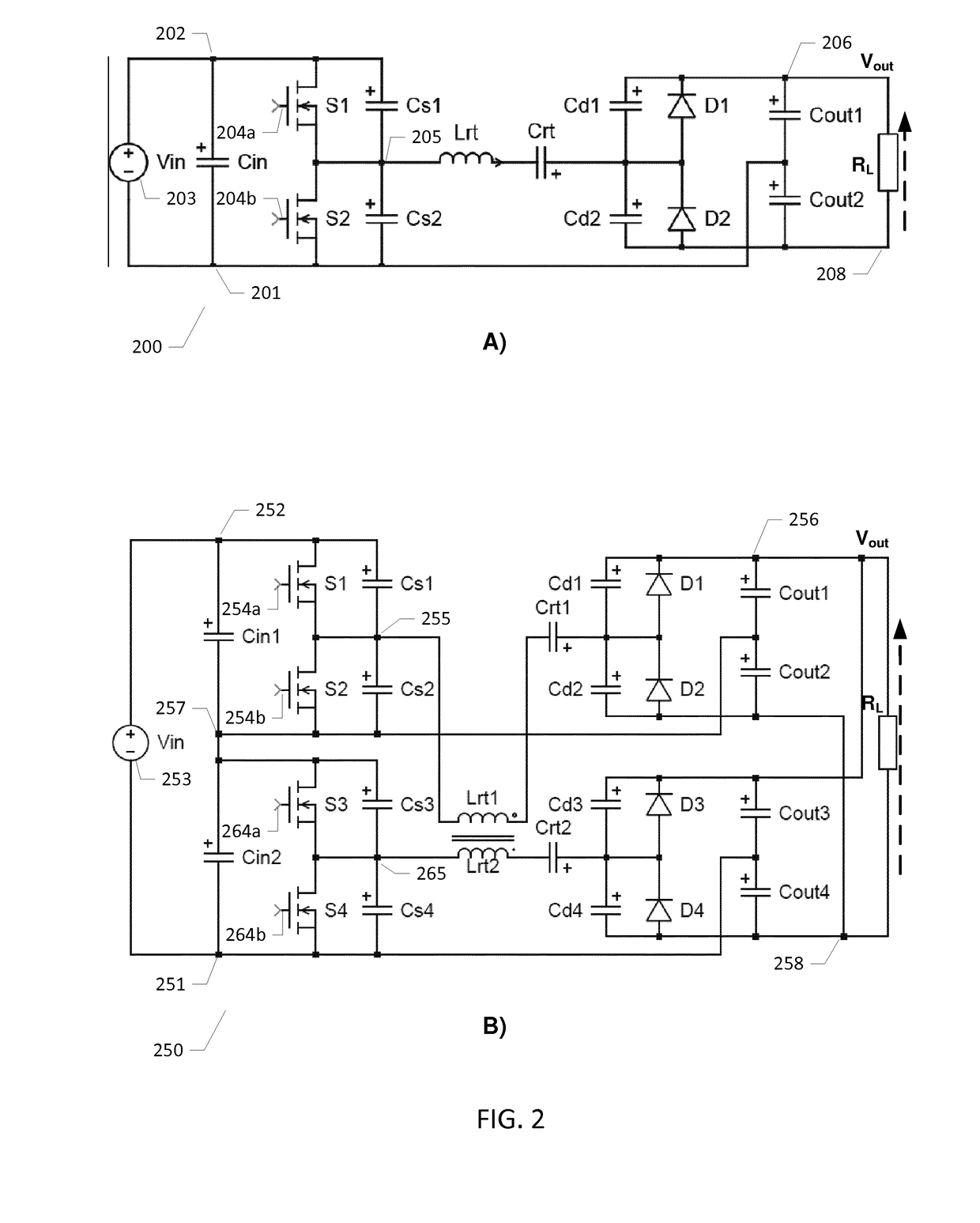
[0056]FIG. 2B) is a simplified electrical circuit diagram of a resonant DC-DC power converter assembly 250 comprising a pair of coupled resonant class DE DC-DC power converters in accordance with the invention. The resonant DC-DC power converter assembly 250 comprises a first class DE power converter built around a first controllable switch arrangement in form of a half-bridge inverter comprising first and second stacked semiconductor switches S1, S2 and a second class DE power converter built around a second controllable switch arrangement in form of a half-bridge inverter comprising third and fourth stacked semiconductor switches S3, S4. The first and second class DE power converters are interconnected, or mutually coupled, via first and second magnetically coupled inductors Lrt1 and Lrt2. Inductors Lrt1 and Lrt2 form part of the respective resonant networks of the first and second class DE power converters. The first and second magnetically coupled inductors Lrt1 and Lrt2 are arr...

third embodiment

[0066]FIG. 3B) is a simplified electrical circuit diagram of a resonant DC-DC power converter assembly 350 comprising first and second magnetically coupled isolated class E self-oscillating resonant DC-DC power converters in accordance with the invention. The resonant DC-DC power converter assembly 350 comprises a first self-oscillating class E power converter built around a first controllable switch arrangement in form of a single semiconductor switch S1 and a substantially identical second self-oscillating class E power converter built around a second controllable semiconductor switch S2. The skilled person will understand that each of the first and second self-oscillating class E power converters may be substantially identical to the above-discussed self-oscillating class E power converter 300. The semiconductor switch S1 of the first class E power converter drives a first resonant network via a driver output 355 or drain terminal. The semiconductor switch S1 is driven by a first...


PUM


Abstract

The present invention relates to a resonant DC-DC power converter assembly comprising a first resonant DC-DC power converter and a second resonant DC-DC power converter having identical circuit topologies. A first inductor of the first resonant DC-DC power converter and a second inductor of the second resonant DC-DC power converter are configured for magnetically coupling the first and second resonant DC-DC power converters to each other to forcing substantially 180 degrees phase shift, or forcing substantially 0 degree phase shift, between corresponding resonant voltage waveforms of the first and second resonant DC-DC power converters. The first and second inductors are corresponding components of the first and second resonant DC-DC power converters.

Description

[0001]The present invention relates to a resonant DC-DC power converter assembly comprising a first resonant DC-DC power converter and a second resonant DC-DC power converter having identical circuit topologies. A first inductor of the first resonant DC-DC power converter and a second inductor of the second resonant DC-DC power converter are configured for magnetically coupling the first and second resonant DC-DC power converters to each other to forcing substantially 180 degrees phase shift, or forcing substantially 0 degree phase shift, between corresponding resonant voltage waveforms of the first and second resonant DC-DC power converters. The first and second inductors are corresponding components of the first and second resonant DC-DC power converters.BACKGROUND OF THE INVENTION[0002]Power density and component costs are key performance metrics of both isolated and non-isolated DC-DC power converters to provide the smallest possible physical size and / or lowest costs for a given...

Claims


Application Information

Patent Timeline
IPC IPC(8): H02M3/335H02M1/44H02M1/14
CPCH02M3/33546H02M1/44H02M1/14H02M3/338H02M7/5383H02M1/0058H02M1/0064H02M3/1557H02M3/1586H02M7/4815H02M1/0043Y02B70/10
Inventor MADSEN, MICKEY P.
Owner DANMARKS TEKNISKE UNIV
Why Eureka
Try Eureka