
Driving support device for vehicle

Active Publication Date: 2017-03-30
TOYOTA JIDOSHA KK
View PDF0 Cites 9 Cited by
  • Summary
  • Abstract
  • Description
  • Claims
  • Application Information

AI Technical Summary

Benefits of technology

This patent describes a system that can correct the steering angle of a vehicle to better match the driver's intentions without changing the desired path. This allows for more accurate driving support without being affected by the driver's steering torque. Additionally, the system can better determine when the driver is not objecting to the steering and set a reference steering angle accordingly. This reduces the drastic change in the driving support torque that might occur if the reference steering angle were to change drastically.

Problems solved by technology

As a result, the intention of the driver is not satisfied.
However, when the predetermined reference value is set to a large value, the magnitude of the steering operation becomes more unlikely to exceed the predetermined reference value.
As a result, when the driver tries to change the traveling lane to, for example, a branch lane, the correction of the target course is delayed.
Thus, it is not possible to appropriately determine the intention of the driver's steering operation through use of the steering angle that is detected with the neutral position being 0.
There is a limitation on an amount of the steering assist torque that can be generated by the electric power steering device, and thus there is also a limitation on the driving support torque (Td).
When the reference steering angle (θs) drastically changes, the indication value (Idsi) also drastically changes, and thus the target driving support torque (Tdt) unavoidably drastically changes.

Method used


Image

  • Driving support device for vehicle
  • Driving support device for vehicle
  • Driving support device for vehicle

Examples


first exemplary embodiment

[0077]Now, referring to the accompanying drawings, exemplary embodiments of the present disclosure are described in detail.

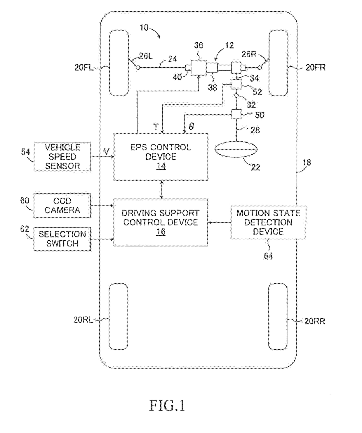
[0078]FIG. 1 is a schematic configuration diagram for illustrating a driving support device 10 according to a first exemplary embodiment of the present disclosure. The driving support device 10 includes an electric power steering (EPS) device 12, an EPS control device 14 serving as a control device configured to control the electric power steering device 12, and a driving support control device 16. The driving support device 10 is applied to a vehicle 18.

[0079]As illustrated in FIG. 1, the vehicle 18 includes front left and right wheels 20FL and 20FR, which are steered wheels, and rear left and right wheels 20RL and 20RR, which are non-steered wheels. The front wheels 20FL and 20FR are steered via a rack bar 24 and tie rods 26L and 26R by the electric power steering device 12 driven in response to an operation by a driver on a steering wheel 22. The steering whe...

second exemplary embodiment

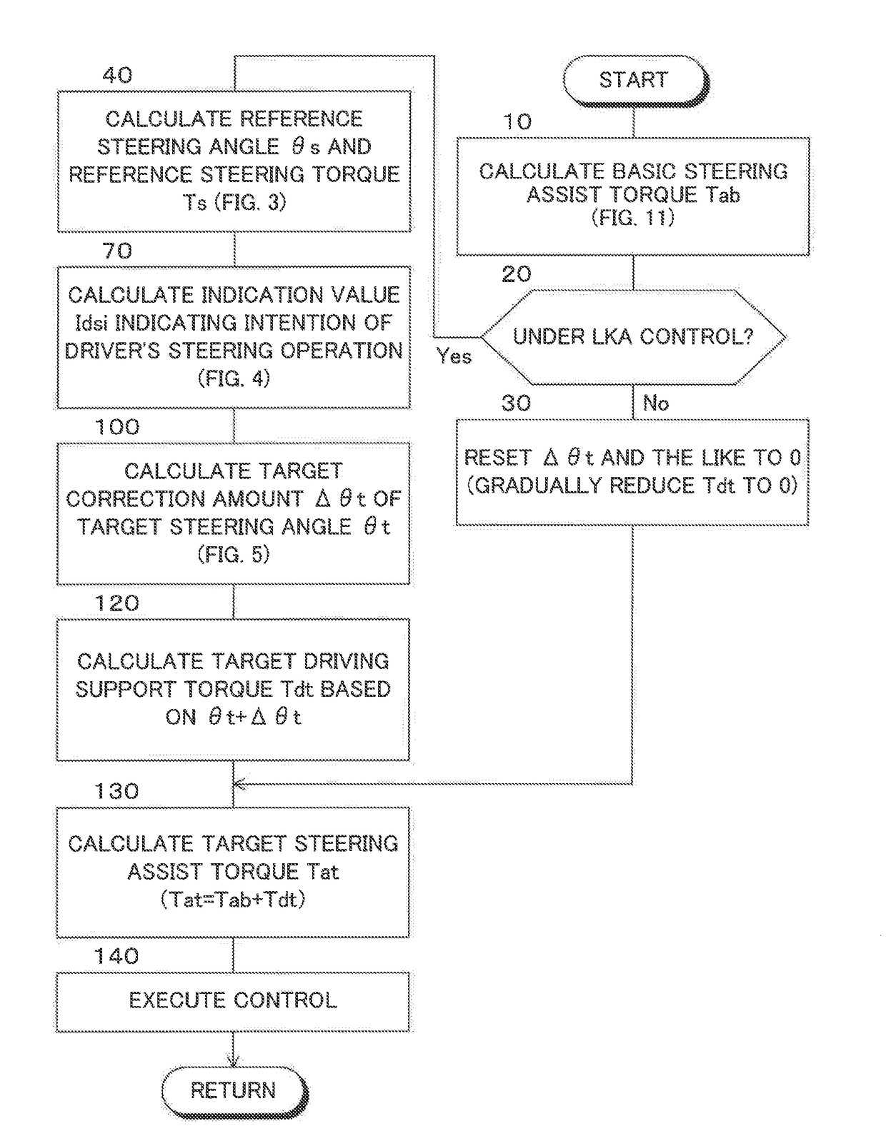
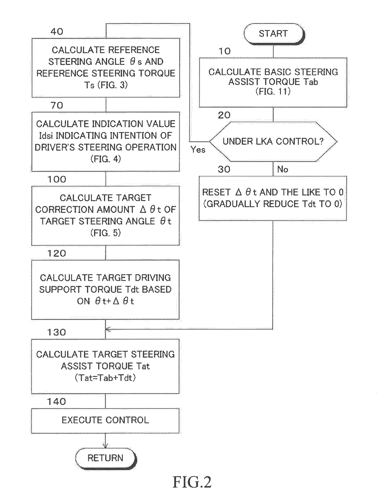
[0164]FIG. 7 is a flowchart for illustrating an exemplary routine for controlling a steering assist torque in an exemplary embodiment of the present disclosure. In FIG. 7, the same step as the step illustrated in FIG. 2 is denoted by the same step number as that assigned in FIG. 2. The same applies to a third exemplary embodiment and first-third modified examples of the present disclosure described later.

[0165]As can be understood from a comparison between FIG. 7 and FIG. 2, in the second exemplary embodiment, the reference steering angle θ s and the reference steering torque Ts are calculated in Step 40 in accordance with the flowchart illustrated in FIG. 8. Steps other than Step 40 of FIG. 7 are executed similarly to the case of the first exemplary embodiment.

[0166]As illustrated in FIG. 8, Steps 42-52 and Steps 58 and 60 are executed similarly to the case of the first exemplary embodiment. In Step 50, when a negative determination is made (No at Step 50), the control proceeds to ...

third exemplary embodiment

[0172]FIG. 9 is a flowchart for illustrating an exemplary routine of controlling a steering assist torque in the third exemplary embodiment.

[0173]In the first exemplary embodiment described above, when the weight coefficients A and B to be used for calculating the first product Pr1 in Step 72 of FIG. 4 are set to 1, the first product Pr1 is calculated in accordance with Expression (1).

Pr1=(θ−θs)(T−Tds)  (1)

[0174]The intention of the driver for transitional steering is considered to be represented by a time derivative dPr1 of the first product Pr1. Thus, Expression (1) is time-differentiated to acquire Expression (2).

dPr1=dθ*(T−Tds)+(θ−θs)*dT  (2)

[0175]Further, Expression (2) is time-integrated to acquire Expression (3). It is understood that the sum of the time integral dθ*(T−Tds) and the time integral (θ−θs)*dT can be acquired as the first product Pr1 from Expression (3).

Pr1=∫Pr1t=∫{θ*(T-s)+(θ-θs)*T}t=∫{θ*(T-Ts)}t+∫{(θ-θs)*T}t (3)

[0176]The product dθ*(T−Tds) of Expression (3) is th...


PUM


Abstract

A driving support device may be configured to calculate a target steering angle for allowing a vehicle to travel along a target course; set, as a reference steering angle, a steering angle when a difference between the steering angle and the target steering angle is small; calculate an indication value indicating intention of a driver's steering operation as a sum of a first product of a corrected steering angle and a steering torque, a second product of a derivative of the corrected steering angle and the steering torque, and a third product of the corrected steering angle and a derivative of the steering torque; and correct the target steering angle based on the indication value so that a target driving support torque is corrected in accordance with the intention of the driver's steering operation.

Description

INCORPORATION BY CROSS REFERENCE TO RELATED APPLICATIONS[0001]Pursuant to 35 U.S.C. §119(a), this application claims the benefit of earlier filing date and right of priority to Japanese Patent Application No. 2015-188868 filed on Sep. 25, 2015, the contents of which, including the specification, drawings and abstract, are incorporated herein by reference in its entirety.BACKGROUND[0002]1. Field[0003]The present disclosure relates to a driving support device for a vehicle, which is configured to control a trajectory of the vehicle.[0004]2. Description of the Related Art[0005]A driving support device configured to control a trajectory of a vehicle includes: a driving support control device configured to calculate a target steering angle for allowing a vehicle to travel along a target course; an electric power steering device configured to generate a steering assist torque; and an electric power steering control device configured to control the electric power steering device. The elect...

Claims


Application Information

Patent Timeline
IPC IPC(8): B62D6/00B62D5/04
CPCB62D5/0463B62D6/002B62D5/046B62D15/025
Inventor KUNIHIRO, YOJIKUDO, YOSHIOKOJO, TAKAHIROSUZUKI, YOSHIAKIUEYAMA, MASAOGOTO, TAKESHIKIMURA, YUKIHIDE
Owner TOYOTA JIDOSHA KK
Learn More