Eureka AIR delivers breakthrough ideas for toughest innovation challenges, trusted by R&D personnel around the world.

Pile foundation visual model test limiting device and using method

A technology of limit device and model test, which is applied in the direction of basic structure test, basic structure engineering, construction, etc., can solve the problems of test difficulty, test deviation, test accuracy reduction, etc., to ensure scientificity, disperse support force, The effect of preventing deviation

Active Publication Date: 2020-11-03
XIAN UNIV OF TECH
View PDF2 Cites 0 Cited by
  • Summary
  • Abstract
  • Description
  • Claims
  • Application Information

AI Technical Summary

Problems solved by technology

[0004] In the existing visual model tests, considering that the normal shooting of the foundation can not be blocked, nor can it hinder its normal movement, the pile foundation is often placed in the model soil directly against the side wall of the model box, and the fine soil particles around the foundation are extremely easy to Into the tiny gap between it and the transparent model box wall, and these soil particles cannot be removed, which brings great difficulties to the test
In addition, due to the lack of model limit devices, the pile foundation model is prone to inclination during the loading process, causing test deviations and greatly reducing test accuracy

Method used


Image

  • Pile foundation visual model test limiting device and using method
  • Pile foundation visual model test limiting device and using method
  • Pile foundation visual model test limiting device and using method

Examples


Embodiment Construction

[0031] The present invention will be described in detail below in conjunction with the accompanying drawings and specific embodiments.

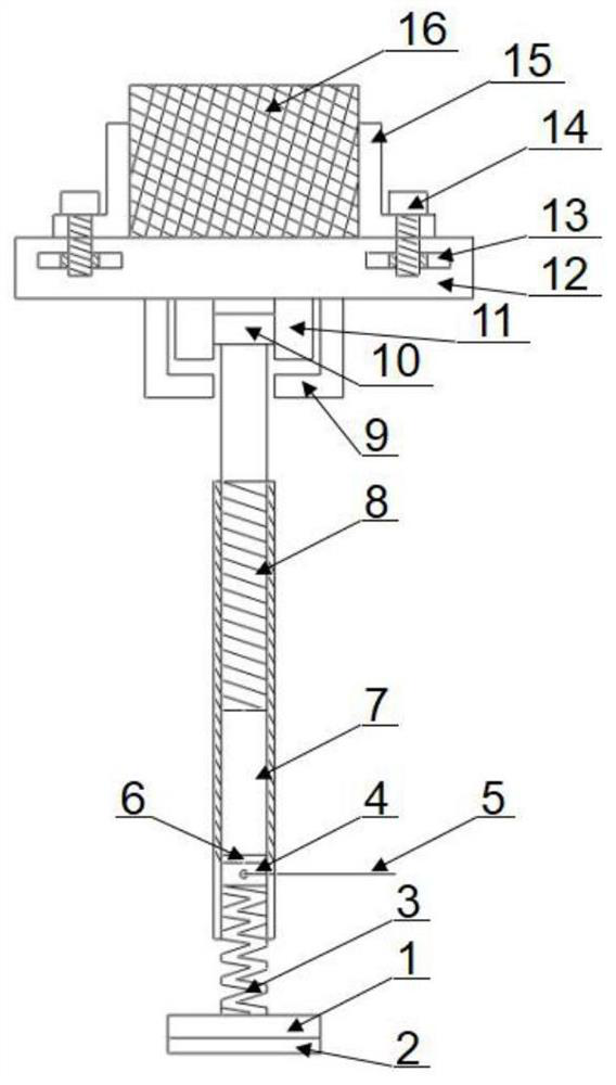
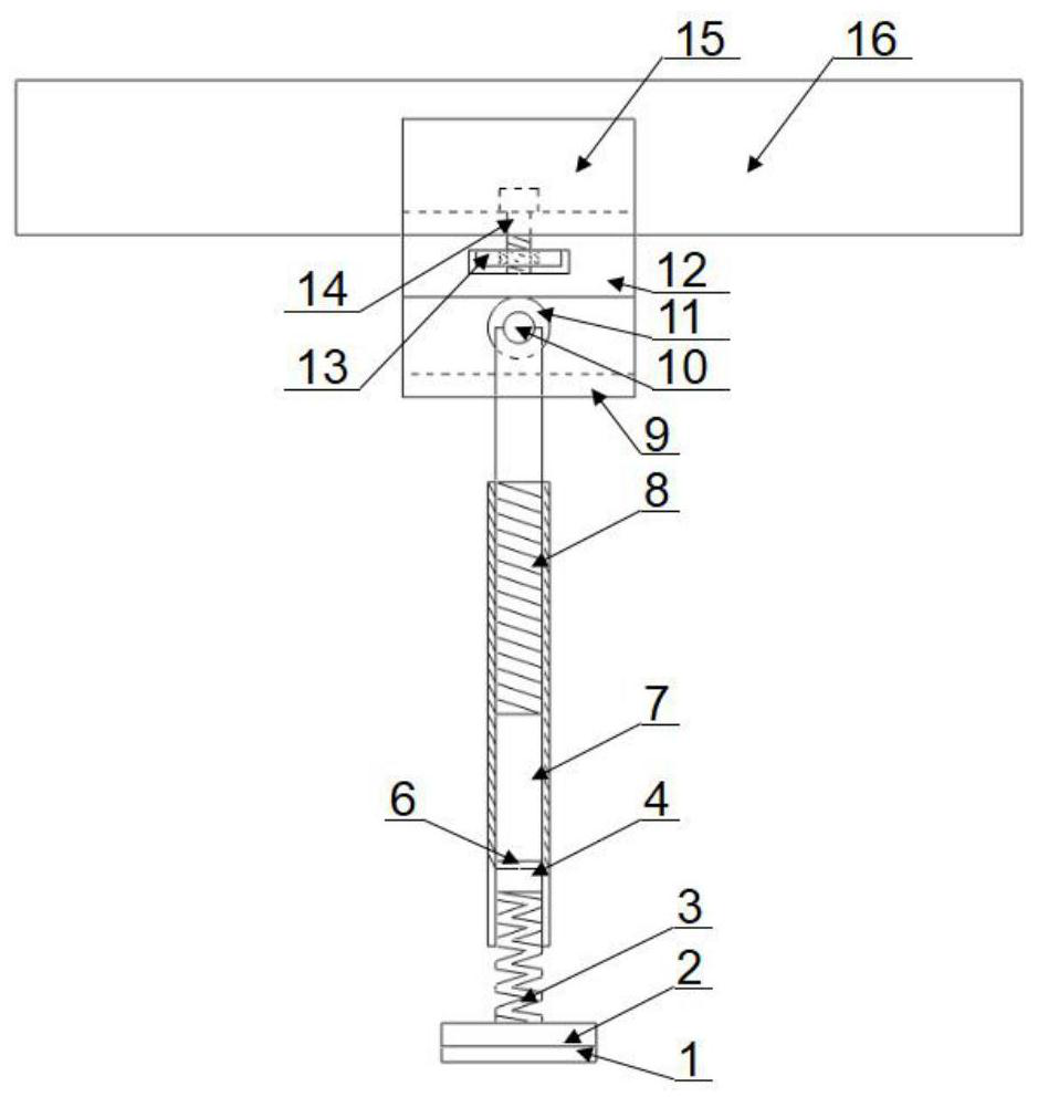
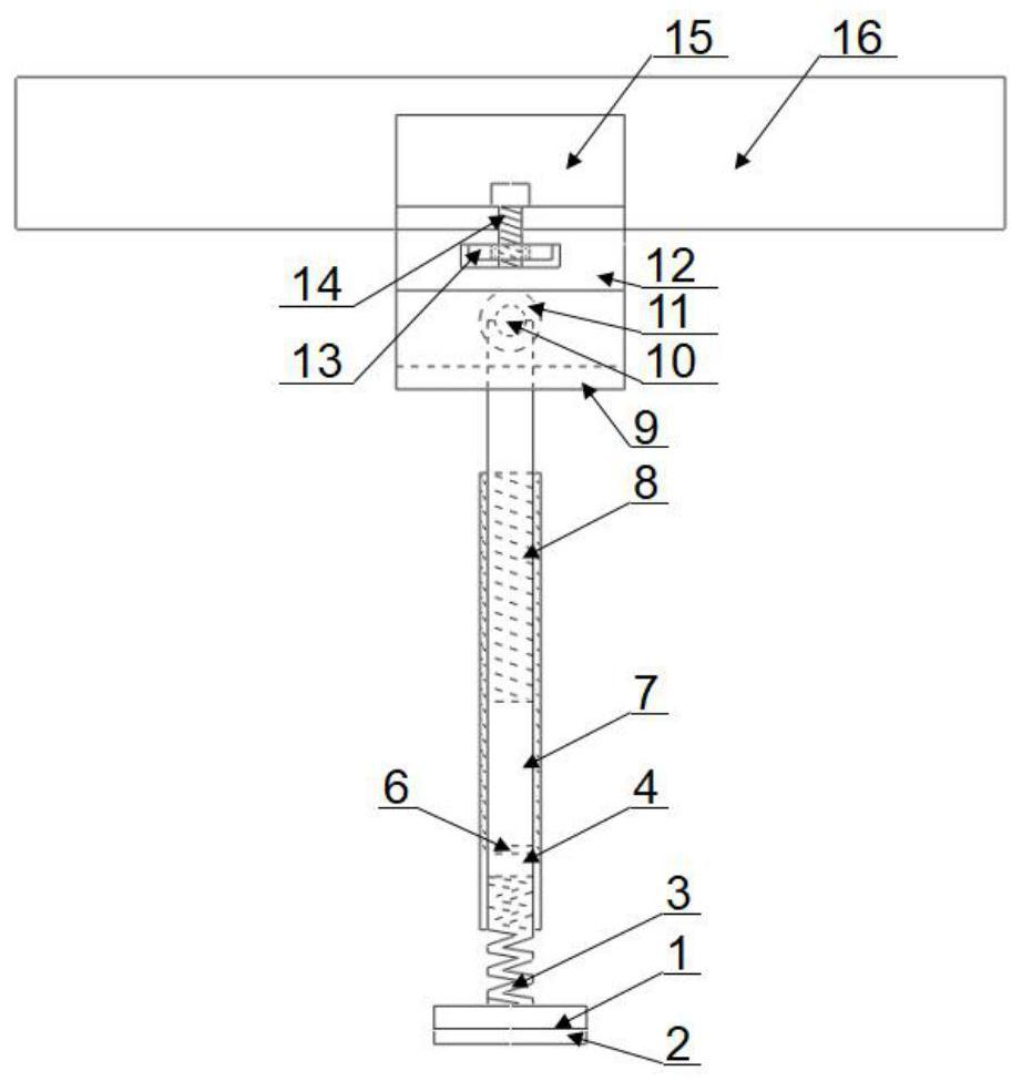
[0032] A pile foundation visual model test limit device, including a chute 12, the upper part of the chute 12 is provided with a model clamp 15; a pile foundation model 16 is arranged in the model clamp 15; the bottom of the chute 12 is provided with a card slot 9; the card slot Wheel shaft 10 is arranged in 9; Wheel shaft 10 two ends are respectively provided with a wheel 11; The middle part of wheel shaft 10 is connected with the upper end of inner thread pipe 7; The lower end is provided with a partition 6; the partition 6 is provided with a miniature pressure sensor 4 and a signal line 5; the other end of the miniature pressure sensor 4 is connected to the upper end of the spring 3; the lower end of the spring 3 is connected to the back plate 1; Equipped with anti-slip rubber pad 2.

[0033] The spring 3 is a cylindrical helical compress...


PUM


Abstract

The invention discloses a pile foundation visual model test limiting device. A model clamp is arranged on a sliding groove, a pile foundation model is arranged in the model clamp; a wheel shaft is arranged in clamping grooves in the bottom of the sliding groove; wheels are arranged at two ends of the wheel shaft; the middle of the wheel shaft is connected with an internal threaded pipe; the internal threaded pipe is connected with a threaded column; a micro pressure sensor and a signal wire are arranged on a partition at the lower end of the internal threaded pipe; the micro pressure sensor isconnected with a spring; the spring is connected with an abutting plate; and an antiskid rubber pad is arranged at the bottom of the abutting plate. The using method comprises the steps of assemblinga limiting device; adjusting the position of the model clamp, and clamping the pile foundation model; putting the pile foundation model into a soil body of a test model box; rotating the internal threaded pipe until the abutting plate and the antiskid rubber pad are abutted against the inner wall of the test model box; finely adjusting and rotating the internal threaded pipe, observing the horizontal supporting force, and stopping rotating when a designed load value is reached; stuffing the test model box with model soil; and applying a load to the pile foundation to finish data acquisition so as to prevent oil particles from entering a fine gap between the foundation and the wall of the transparent model box.

Description

technical field [0001] The invention belongs to the technical field of limiting devices for foundation engineering construction, and in particular relates to a limiting device for a pile foundation visualization model test and a use method thereof. Background technique [0002] With the vigorous development of my country's infrastructure construction, there are more and more railway, highway, bridge and wharf construction projects, and they are constantly being carried out in remote and difficult areas. The pile foundation can transmit the load of the superstructure to the soil around the pile and the deep foundation, the structure is reliable, and the settlement of the foundation is greatly reduced. Practice has proved that the pile foundation is a safe and reliable foundation form, and it has been widely used in bridge structures crossing rivers, rivers, lakes and lakes and waterfront wharves in China. [0003] The model test method is one of the important methods of basi...

Claims


Application Information

Patent Timeline
Patent Type & Authority Applications(China)
IPC IPC(8): E02D33/00
CPCE02D33/00
Inventor 陈阳赵文金文强
Owner XIAN UNIV OF TECH
Why Eureka
Eureka Blog
Learn More