Reception apparatus

Active Publication Date: 2017-03-30
CANON KK
View PDF11 Cites 8 Cited by
  • Summary
  • Abstract
  • Description
  • Claims
  • Application Information

AI Technical Summary

Benefits of technology

[0008]The present invention has been made in order to solve the above-described problems. Therefore, an object of the present invention is to provide a reception apparatus capab

Problems solved by technology

Therefore, in a case of a small-sized paper, there is a concern about damages associated with falling, and in a case of a paper having curling tendency, the paper can scratch a surface of another paper that has been already received.
In a case of a front discharge mode, the generation of the damages during discharge can be suppressed, but there is a concern that the reception sheet cannot receive the paper having slid down on an inclined portion.
In order to avoid this, role paper

Method used


Image

  • Reception apparatus
  • Reception apparatus
  • Reception apparatus

Examples


Example

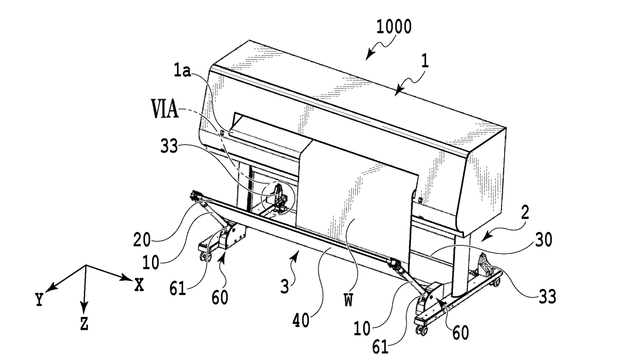
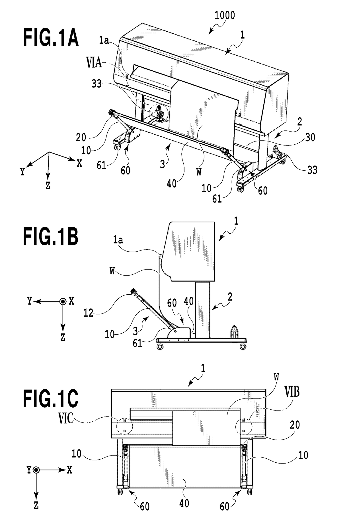
[0036]FIGS. 1A to 1C illustrate an external view of a print apparatus 1000 that can be used as a reception apparatus of the present invention. FIG. 1A is a perspective view of the print apparatus 1000, FIG. 1B is a side view thereof, and FIG. 1C is a front view thereof. The print apparatus 1000 mainly includes a printer unit 1, a leg unit 2 supporting the printer unit 1, and a reception unit 3 receiving a print medium discharged from a discharge port 1a of the printer unit 1.

[0037]The printer unit 1 includes a print medium W held in a rolled shape, a print head capable of printing an image on the print medium W, a cutter cutting the print medium W for each printed page, and the like. The print medium W including a region in which a predetermined image is printed by a print head is gradually discharged via the discharge port 1a along with the advance of a print operation, and hangs down from the discharge port 1a in a Z direction due to its own weight. Then, in a case where a cutter ...


PUM


Abstract

A reception apparatus that receives an article discharged from a processing apparatus includes a first rod, second rod and a reception sheet. The first rod extends in a direction crossing a direction of the discharge below a discharge port of the processing apparatus in a gravity direction. The second rod extends in the direction crossing the direction of the discharge at a position farther away from the discharge port than the first rod. The reception sheet has flexibility, is supported by the first rod and the second rod, and receives the article discharged between the first rod and the second rod. The first rod is capable of being disposed at a first position and a second position which are different from each other in the gravity direction.

Description

BACKGROUND OF THE INVENTION[0001]Field of the Invention[0002]The present invention relates to a reception apparatus receiving an article discharged from a processing apparatus such as a printer.[0003]Description of the Related Art[0004]Japanese Patent Laid-Open No. 2009-242111 discloses a configuration in which a position of a flexible sheet for receiving papers discharged from a printer is appropriately changed depending on a type and a size of the paper. Specifically, a size and a depth of a reception region of the large sheet can be adjusted by arranging a shaft mounted on a leading end or a middle portion of flexible large sheet at various positions, and winding the large sheet on the shaft.[0005]However, in first and second rear discharge modes according to Japanese Patent Laid-Open No. 2009-242111, a distance in a gravity direction from a paper-discharging portion to a reception sheet receiving the paper is large. Therefore, in a case of a small-sized paper, there is a concern...

Claims


Application Information

Patent Timeline
IPC IPC(8): B65H31/04B65H16/00B41J15/04
CPCB65H31/04B65H16/005B41J15/04B65H31/00B65H2801/03B41J13/106B65H31/02B65H31/20B65H2401/14B65H2405/1116B65H2701/11312B65H2801/36B41J11/0045B41J11/36B41J13/02B41J13/26
Inventor ASAI, YASUYUKIYONEYAMA, HIROMASAANAYAMA, DAIKI
Owner CANON KK
Why Eureka
Try Eureka