In-Cell Touch Display Device

a display device and in-cell technology, applied in the field of touch sensitive display devices, can solve the problems of reducing difficult to achieve a slim device, and limiting so as to reduce the width of the bezel area

Active Publication Date: 2017-03-30
LG DISPLAY CO LTD
View PDF9 Cites 17 Cited by
  • Summary
  • Abstract
  • Description
  • Claims
  • Application Information

AI Technical Summary

Benefits of technology

[0012]An object of the present disclosure is to provide an in-cell touch display device capable of reducin...

Problems solved by technology

In this case, there is a limit to how much the width of the bezel area can be decreased and thus it is difficult to achieve a slim device.
Even in this case, there is a limit to how much the width of the bezel area can...

Method used


Image

  • In-Cell Touch Display Device
  • In-Cell Touch Display Device
  • In-Cell Touch Display Device

Examples


Embodiment Construction

[0031]In the specification, it will be understood that, when an element is referred to as being “on” another element, it can be directly on the other element or intervening elements may be present therebetween.

[0032]Furthermore, the use of the ordinal numbers “first”, “second”, “third”, etc., to describe an element merely indicates that different instances of like elements are being referred to, and are not intended to imply that the elements so described must be in a given sequence.

[0033]An in-cell touch display device according to an embodiment of the present disclosure will be described in detail with reference to the attached drawings.

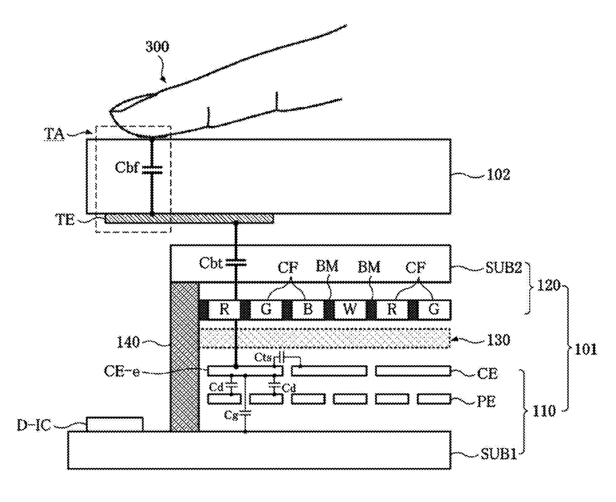
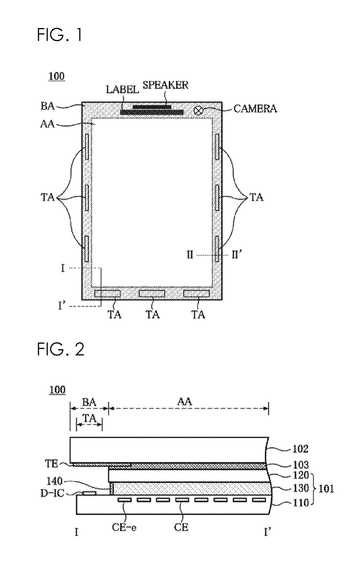
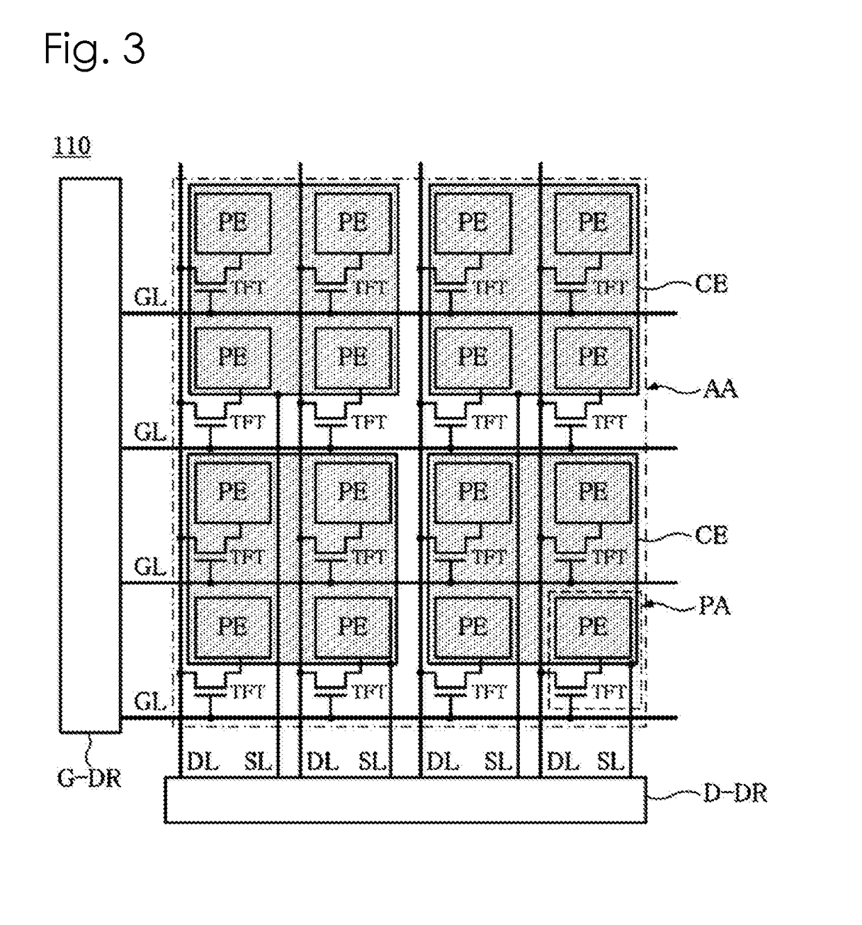
[0034]FIG. 1 is a plan view of an in-cell touch device according to an embodiment of the present disclosure, FIG. 2 is a cross-sectional view taken along line I-I′ of FIG. 1 and FIG. 3 is a plan view showing part of a first substrate of FIG. 2. FIG. 4A is a diagram illustrating a case in which touch is not applied to part of a display area of FIG. ...


PUM


Abstract

A touch display device capable of reducing the width of a bezel area and achieving a slim device while arranging touch type button keys in the bezel area. The touch display device may be an in-cell touch display device that include at least one touch electrode located on a cover glass, corresponding to one or more touch key areas separated at intervals in a bezel area, extended to a display area and overlapping with a common electrode neighboring the touch key area from among the plurality of common electrodes. Accordingly, when a touch key area is touched, the voltage of a common electrode overlapping the touch electrode changes to sense whether the touch key area is touched, and thus there may not be a need to provide an additional touch panel and an additional touch driving circuit to the bezel area.

Description

CROSS REFERENCE TO RELATED APPLICATION[0001]This application claims the benefit of Korean Patent Application No. 10-2015-0138060, filed on Sep. 30, 2015, which is hereby incorporated by reference as if fully set forth herein.BACKGROUND[0002]Field[0003]The present disclosure relates to a touch sensitive display device for sensing touch using a common electrode of a display panel.[0004]Discussion of the Related Art[0005]With the advent of the information age, display technology for visually displaying electrical information signals is under rapid development. Accordingly, efforts to decrease the volume, weight and power consumption of flat display devices have been made.[0006]Typical examples of such flat display devices may include a liquid crystal display (LCD), a plasma display panel (PDP), a field emission display (FED), an electroluminescence display (ELD), an electrowetting display (EWD), an organic light emitting diode (OLED) display and the like.[0007]In display devices, such ...

Claims


Application Information

Patent Timeline
IPC IPC(8): G02F1/1333G06F3/047G06F3/044G06F3/041G02F1/1339G02F1/1362G02F1/1343
CPCG02F1/133308G02F1/1368G06F3/047G02F1/134309G06F3/0416G02F1/133345G02F1/1339G06F3/044G06F3/0412G02F1/13338G02F2201/121G02F2001/133331G02F2201/123G02F2203/04G02F1/133514G02F1/136286G06F2203/04103G06F3/0445G06F3/04166G02F1/133388G02F1/133331
Inventor JUNG, YEOUN-JEI
Owner LG DISPLAY CO LTD
Why Eureka
Try Eureka