Online compensation of thermal distortions in a stereo depth camera

a depth camera and thermal distortion technology, applied in image enhancement, image analysis, instruments, etc., can solve the problems of consuming power, area and cost, and weak approach for real products, and generating errors in determined depth

Active Publication Date: 2017-03-30
INTEL CORP
View PDF1 Cites 28 Cited by
  • Summary
  • Abstract
  • Description
  • Claims
  • Application Information

AI Technical Summary

Problems solved by technology

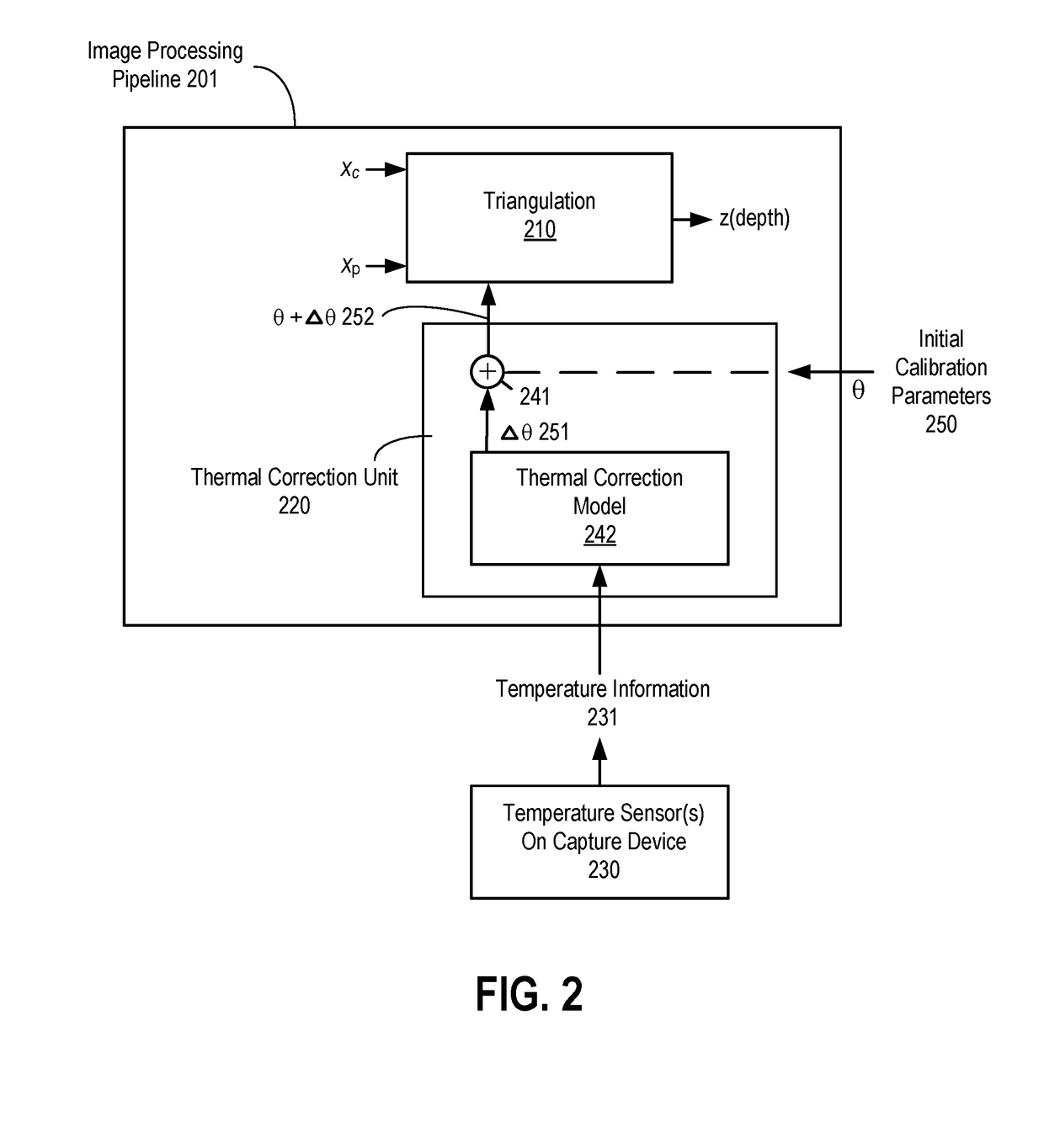
Temperature variations may cause changes in the parameters, thereby causing errors in the determined depth generated by the triangulation process.
The former approach is very weak for a real product since it implies a narrow working temperature range and the system being at the “working point” where the temperature is stable.
The active thermal control allows correct operation in a wider range of temperatures, yet it consumes power, area and cost, which are all undesirable.

Method used


Image

  • Online compensation of thermal distortions in a stereo depth camera
  • Online compensation of thermal distortions in a stereo depth camera
  • Online compensation of thermal distortions in a stereo depth camera

Examples


Embodiment Construction

[0013]In the following description, numerous details are set forth to provide a more thorough explanation of the present invention. It will be apparent, however, to one skilled in the art, that the present invention may be practiced without these specific details. In other instances, well-known structures and devices are shown in block diagram form, rather than in detail, in order to avoid obscuring the present invention.

[0014]The description may use the phrases “in an embodiment,” or “in embodiments,” which may each refer to one or more of the same or different embodiments. Furthermore, the terms “comprising,”“including,”“having,” and the like, as used with respect to embodiments of the present disclosure, are synonymous.

[0015]The term “coupled with,” along with its derivatives, may be used herein. “Coupled” may mean one or more of the following. “Coupled” may mean that two or more elements are in direct physical, electrical, or optical contact. However, “coupled” may also mean tha...


PUM


Abstract

A method and apparatus for performing temperature compensation for thermal distortions in a camera system. In one embodiment, the system comprises a first camera configured to capture a sequence of images of the object; a second device; a processing unit to receive the sequence of images and determine depth information in response to parameters of the camera and the second device; one or more temperature sensors; and a thermal correction unit responsive to temperature information from the one or more temperature sensors to adjust one or more of the calibration parameters of the first camera and the second device.

Description

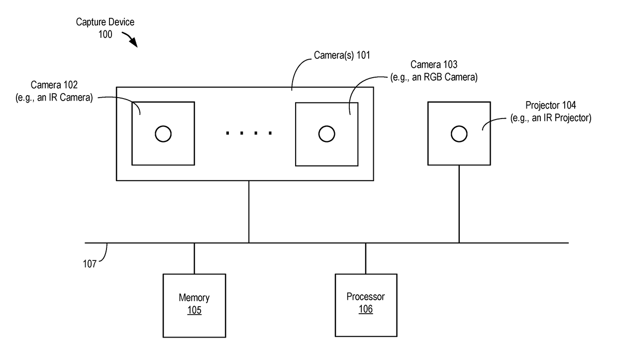
FIELD OF THE INVENTION[0001]Embodiments of the present invention relate to the field of camera systems that perform three-dimensional (3-D) measurements by use of active or passive triangulation capturing one or more images with or without the assistance of one or more patterns projected by a projector; more particularly, embodiments of the present invention relate to performing temperature compensation of such camera systems.BACKGROUND OF THE INVENTION[0002]Stereo depth cameras are well-known and are often used to measure a distance from an object. As part of the process, images of scenes are captured and measurements are taken to determine depth information. One method of determining the depth of objects in a scene from a captured image is made using triangulation.[0003]In order to perform triangulation accurately, some calibration of the stereo depth camera is typically performed at assembly time. Calibration sets some intrinsic and extrinsic parameters of the stereo camera. Subs...

Claims


Application Information

Patent Timeline
Patent Type & Authority Applications(United States)
IPC IPC(8): H04N13/02
CPCH04N13/0246H04N2013/0081H04N13/0253H04N13/025G06F3/0488G06F3/012G06F3/017G06T5/006G06T7/85H04N13/243H04N13/246H04N13/25H04N13/254
Inventor ZABATANI, AVIADBAREKET, SAGYMENASHE, OHADSPERLING, EREZBRONSTEIN, ALEXBRONSTEIN, MICHAELKIMMEL, RONSURAZHSKY, VITALY
Owner INTEL CORP
Why Eureka
Try Eureka