Surgical micro-shears and methods of fabrication and use

a micro-shear and micro-shear technology, applied in the field of micro- and millimeter-scale tissue debridement devices, can solve the problems of relatively large dimensions of the debrider device, affecting the treatment effect, and so as to achieve the effect of cutting and/or removing unintended tissue from the subject, and reducing the risk of unintended tissue removal

Inactive Publication Date: 2017-04-06
MICROFAB
View PDF6 Cites 11 Cited by
  • Summary
  • Abstract
  • Description
  • Claims
  • Application Information

AI Technical Summary

Benefits of technology

The present invention relates to methods and devices for tissue removal in medical applications. One embodiment is a powered scissors device that includes a distal housing, an elongate member, a rotary blade, and a gear system. The device has a fixed cutting arm and a rotatable blade with cutting elements that cooperate with the fixed arm to shear tissue therebetween. The rotatable blade is located inside the distal housing and has an axis of rotation perpendicular to the inner drive tube. The cutting element is shorter than the fixed arm and has a curved cutting edge that interacts with the fixed arm's cutting edge. The device can be fabricated using several layers of structural and sacrificial materials, where the sacrificial material is removed to reveal the three-dimensional structure. Other aspects of the invention include the use of etching holes and the separation of components during fabrication. The technical effect of the present invention is to provide a powered scissors device with improved cutting performance and ease of use in medical applications involving tissue removal.

Problems solved by technology

Some debrider devices with relatively large dimensions risk removing unintended tissue from the subject, or damaging the unintended tissue.
Some devices with relatively large dimensions risk cutting and / or removing unintended tissue from the subject, or damaging the unintended tissue.

Method used


Image

  • Surgical micro-shears and methods of fabrication and use
  • Surgical micro-shears and methods of fabrication and use
  • Surgical micro-shears and methods of fabrication and use

Examples


Embodiment Construction

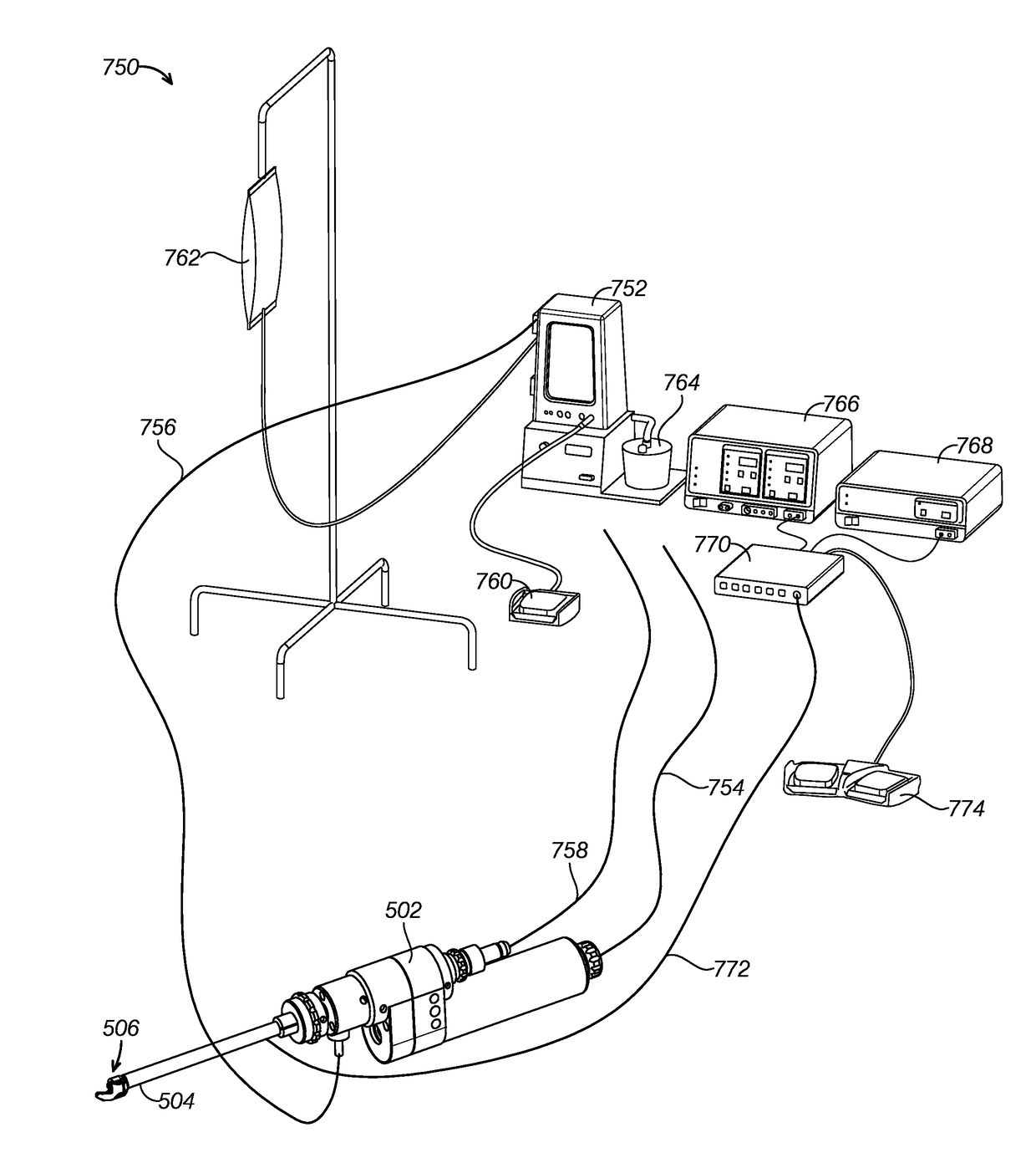
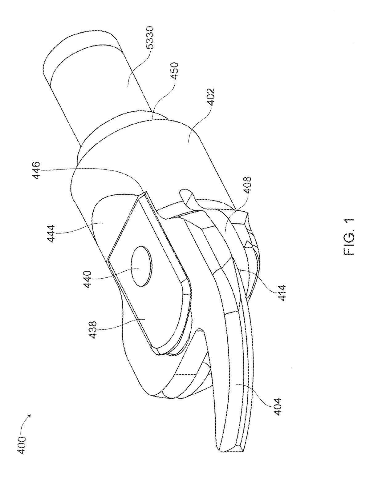
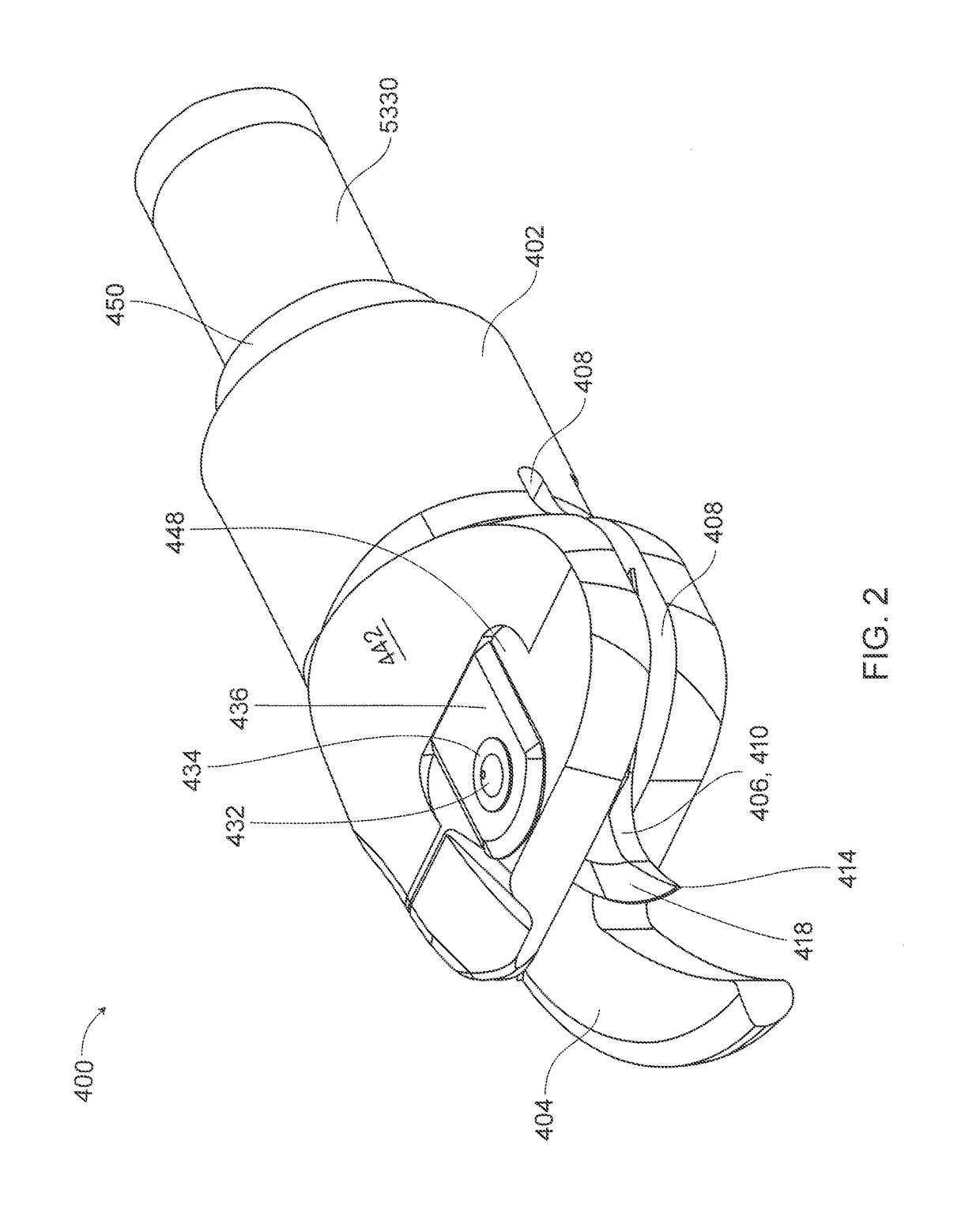
[0052]FIGS. 1-9 show a first exemplary embodiment of a tissue cutting device constructed according to aspects of the present disclosure. Device 400 is a powered scissors construct that may be coupled to the distal end of any elongate member configured to introduce the device to a target tissue site of a subject, such as the motorized handpiece 502 shown in FIG. 10, or the fixed or articulating shafts disclosed in U.S. Patent Application Publication 2014 / 0100558. FIGS. 1 and 2 are top and bottom perspective views, respectively, showing the overall construction of device 400. As shown in these figures, device 400 includes a distal housing or lug 402 provided with a distally extending, arcuate, fixed arm or horn 404. Rotating blade 406 is rotatably mounted within slot 408 that traverses the distal end of lug 402, as best seen in FIG. 7. Blade 406 is provided with four arcuate cutting elements 410 (as best seen in FIG. 6) that capture and shear tissue in turn between each cutting elemen...


PUM


Abstract

Methods and devices are provided for use in medical applications involving tissue removal. One exemplary powered scissors device includes a distal housing having a fixed cutting arm located thereon, an elongate member coupled to the distal housing and configured to introduce the distal housing to a target tissue site of the subject, a rotatable blade rotatably mounted to the distal housing, the rotatable blade having at least one cutting element configured to cooperate with the fixed arm to shear tissue therebetween, a crown gear located at a distal end of an inner drive tube, and a first spur gear configured to inter-engage with the crown gear and coupled with the rotatable blade to allow the crown gear to drive the rotatable blade.

Description

CROSS REFERENCE TO RELATED APPLICATIONS[0001]This application is a continuation-in-part of U.S. application Ser. No. 13 / 855,627 filed Apr. 2, 2013 which claims benefit of U.S. Provisional Application No. 61 / 710,608 filed Oct. 5, 2012. This application also claims the benefit of U.S. Provisional Application No. 62 / 385,829 filed Sep. 9, 2016.[0002]This application is related to the following U.S. applications: application Ser. No. 15 / 167,899 filed May 27, 2016; Provisional Application No. 62 / 167,262 filed May 27, 2015; application Ser. No. 13 / 843,462 filed Mar. 15, 2013; application Ser. No. 13 / 535,197 filed Jun. 27, 2012, now U.S. Pat. No. 9,451,977; application Ser. No. 13 / 388,653 filed Apr. 16, 2012; application Ser. No. 13 / 289,994 filed Nov. 4, 2011, now U.S. Pat. No. 8,475,483; application Ser. No. 13 / 007,578 filed Jan. 14, 2011; application Ser. No. 12 / 491,220 filed Jun. 24, 2009, now U.S. Pat. No. 8,795,278; application Ser. No. 12 / 490,301 filed Jun. 23, 2009, now U.S. Pat. No....

Claims


Application Information

Patent Timeline
IPC IPC(8): A61B17/3201A61B18/14A61B34/30A61B17/3205A61N1/36A61B17/32A61B18/12
CPCA61B2017/00039A61B2017/00398A61B2217/005A61B2217/007A61B2018/00982A61B2018/00839A61B2018/00642A61B2018/00702A61B2018/00601A61B2018/00607A61B2018/00595A61B2018/00494A61B2018/146A61B2018/1253A61B2018/126A61B2034/305B33Y10/00B33Y80/00C25D1/003A61B17/3201A61B17/32002A61B18/1447A61B18/1206A61B17/32056A61N1/36A61B34/30A61B2017/00818A61B18/1445A61B2017/00269A61B2017/320032A61B18/1492A61B2218/002A61B2018/1467A61N1/05A61N1/36014
Inventor SCHMITZ, GREGORY P.WU, MING-TINGMILLER, ERIC C.PEREA, JUAN DIEGO
Owner MICROFAB
Why Eureka
Try Eureka