

Radial head prosthesis with rotate-to-lock interface
- Summary
- Abstract
- Description
- Claims
- Application Information
AI Technical Summary
Benefits of technology
Problems solved by technology
Method used
Image

Examples
Embodiment Construction
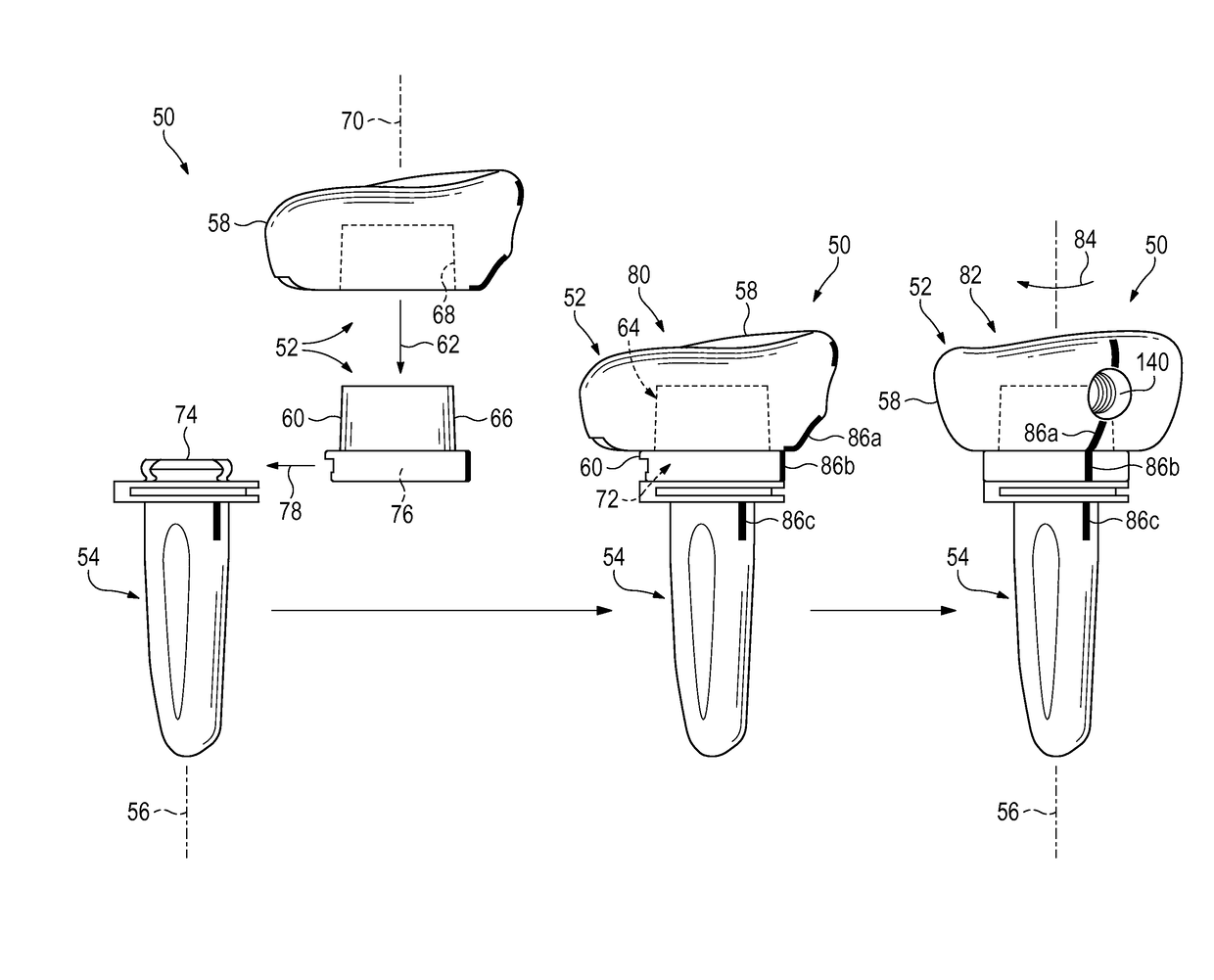
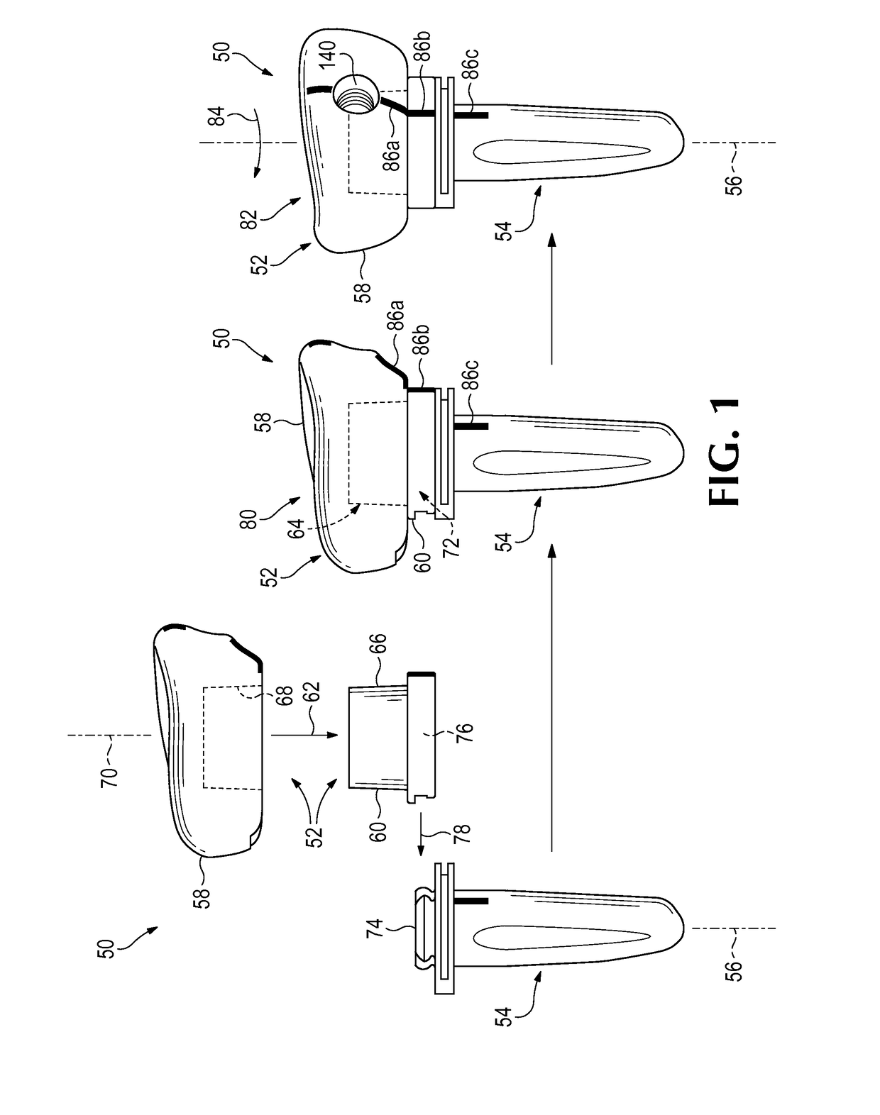
[0029]The present disclosure provides a system, including methods and apparatus, for replacing an end of a bone, such as a radial bone, with a prosthesis. In exemplary embodiments, the prosthesis is a radial head prosthesis having a stem portion and a head portion. The head portion may be configured to be (a) placed onto the stem portion by movement of the head and stem portions relative to one another transverse to a longitudinal axis of the stem portion, and then (b) rotated with respect to the stem portion to produce friction that firmly attaches the head portion to the stem portion.
[0030]The prosthesis disclosed herein may have substantial advantages over other prostheses. The head and stem portions may be locked to one another without a set screw, which can back out after the prosthesis has been implanted in a subject. Furthermore, the head portion may be provisionally assembled with the stem portion by sliding the head portion onto the stem portion via a transverse (and option...
PUM
 Abstract
Description
Claims
Application Information