
Tensile Resistant Light String

Inactive Publication Date: 2017-04-13
POLESTAR ELECTRIC IND
View PDF6 Cites 0 Cited by
  • Summary
  • Abstract
  • Description
  • Claims
  • Application Information

AI Technical Summary

Benefits of technology

The invention increases the strength of the wires in a light string without making the string heavier or more expensive. This allows for the light string to be used in a wider range of applications.

Problems solved by technology

However, as the number of the illuminating units increases, the regular wire cannot afford the total weight of the illuminating units.
However, using the assistant line greatly increases the cost and complicates the manufacturing process of the decorative illuminating device with assistant line.
Besides, the total weight of the decorative illuminating device with assistant line is also greatly increased, which limits the application and usage of the decorative illuminating device with assistant line.

Method used


Image

  • Tensile Resistant Light String
  • Tensile Resistant Light String
  • Tensile Resistant Light String

Examples


Embodiment Construction

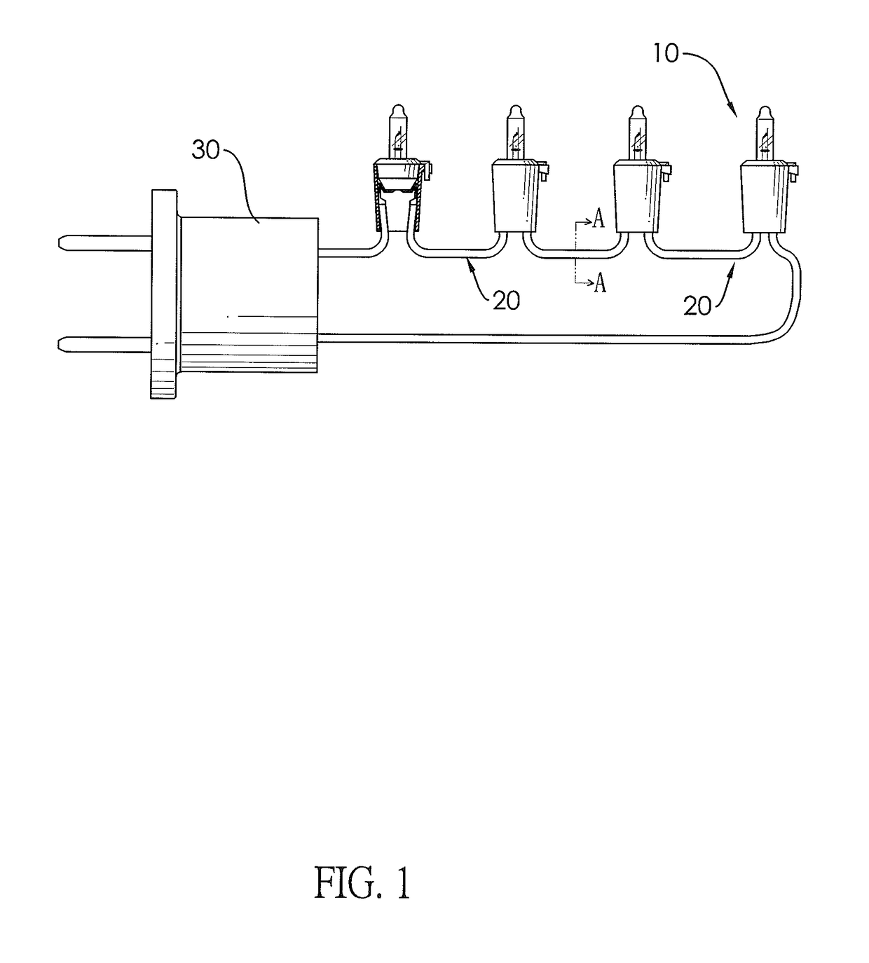
[0020]With reference to FIG. 1, the tensile resistant light string in accordance with the present invention comprises multiple illuminating units 10, multiple wires 20, and a plug 30.

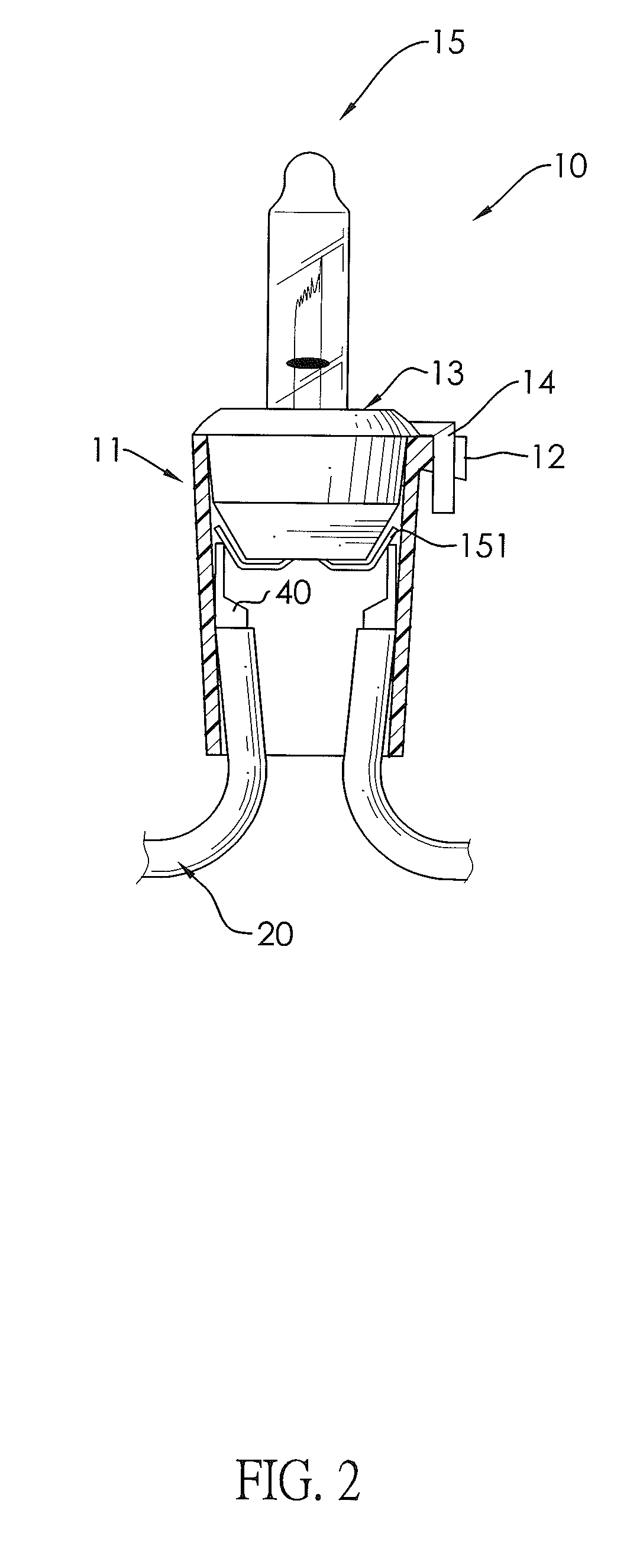
[0021]With reference to FIG. 2 and FIG. 3, each one of the illuminating units 10 is an incandescent lamp and comprises a cover 11, a receiving portion 12, a holder 13, a hook 14, and a bulb 15.

[0022]The cover 11 has a top opening 111, a bottom opening 112, a space 113, an inner wall 114, and an outer wall 115. The top opening 111 is located at the top of the cover 11. The bottom opening 112 is opposite the top opening 111 and is located at the bottom of the cover 11. The space 113 is located within the cover 11 and communicates with the top opening 111 and the bottom opening 112. The inner wall 114 is opposite the outer wall 115. The inner wall 114 is faced to the space 113.

[0023]The receiving portion 12 is mounted on the outer wall 115 of the cover 11 and is next to the top opening 111.

[0024]The holder...


PUM

PropertyMeasurementUnit
Electrical resistanceaaaaaaaaaa
Tensile propertiesaaaaaaaaaa

Abstract

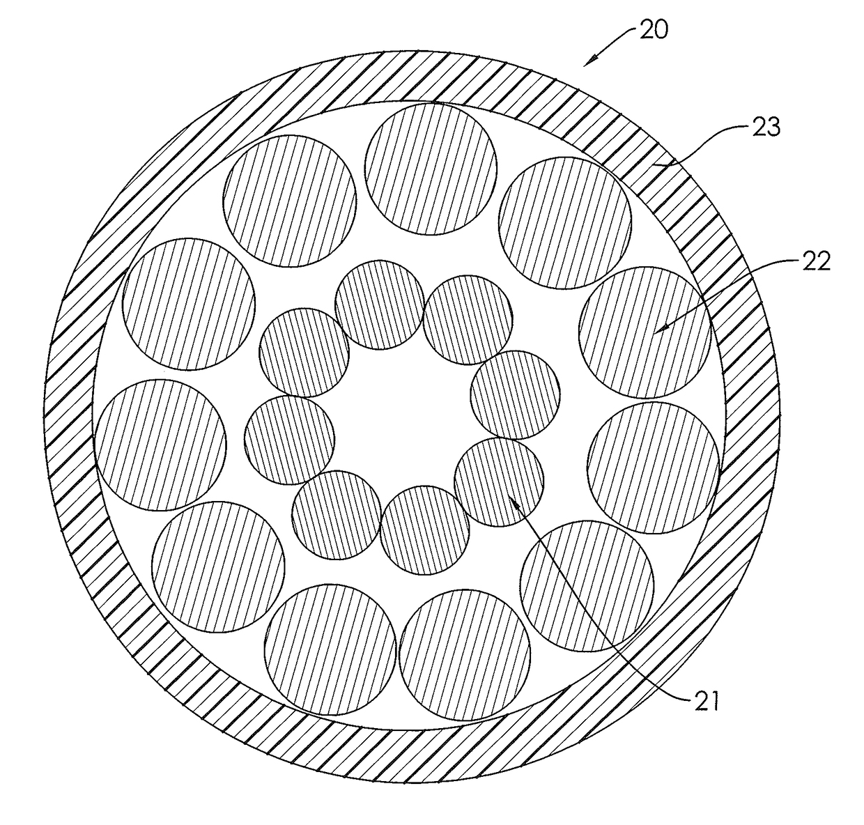
The present invention provides a tensile resistant light string comprising: multiple illuminating units electrically connected by multiple wires, wherein each one of the wires comprising: a tensile resistant layer; a conductive layer wrapping the tensile resistant layer, and an insulating layer wrapping the conductive layer; and wherein the insulating layer is made of cotton fiber, the conductive layer is consisting of multiple metal lines, the metal lines are made of copper, the tensile resistant layer is consisting of at least one line. The tensile resistance of the wires is enhanced by the tensile resistant layer.

Description

CROSS-REFERENCE TO RELATED APPLICATIONS[0001]This application is based upon and claims priority under 35 U.S.C. 119(a) from China Patent Application No. 201520790162.X filed on Oct. 13, 2015, which is hereby specifically incorporated herein by this referenced thereto.BACKGROUND[0002]1. Technical Field[0003]The present invention relates to a decorative illuminating device, especially to a light string.[0004]2. Description of the Prior Art(s)[0005]A conventional decorative illuminating device, hung up on a tree or other objects to form a beautiful decoration, is consisted of a regular wire and multiple illuminating units connected by the regular wire. However, as the number of the illuminating units increases, the regular wire cannot afford the total weight of the illuminating units. To overcome this problem, a decorative illuminating device with assistant line is developed. An assistant line without electric conductive function is entwined with the regular wire to enhance the tensile...

Claims


Application Information

Patent Timeline
IPC IPC(8): F21V23/00F21V23/06H01B1/02H01B7/04F21S4/10H01B3/30
CPCF21V23/001F21S4/10F21V23/06H01B1/02H01B7/04H01B3/30F21W2121/04F21Y2115/10H01B7/18
Inventor CHANG, CHENG-TAOCHANG, CHU-CHENGCHANG, CHENG-FEN
Owner POLESTAR ELECTRIC IND
Learn More