Row unit downforce control

a row unit and downforce technology, applied in agricultural machinery, applications, agricultural tools and machines, etc., can solve the problems of inability to accurately and predictably control the system, too much downforce, and inability to accurately place seeds or seed placement on the soil surfa

Inactive Publication Date: 2017-04-20
STRAETER JAMES E
View PDF1 Cites 0 Cited by
  • Summary
  • Abstract
  • Description
  • Claims
  • Application Information

AI Technical Summary

Benefits of technology

This patent describes a control assembly for a row unit used in agricultural machines. The assembly has a linkage that connects to a tool bar and the row unit, allowing for adjustment of the downward force. A locator is also included, which has slots and rollers to control the movement of the unit. An actuator is connected to the locator to act on the downward force adjustment. The technical effect of this invention is to provide a better control system for the row unit, which improves the performance of the agricultural machine.

Problems solved by technology

Inadequate downforce can result in shallow seed placement or seed placement on the soil surface.
Too much downforce overly compacts the seed bed or forms a deep seed furrow that deters early plant development.
Springs and airbags have been used to create downforce, but these systems lack accuracy and predictability.
Other systems use expensive and complex hydraulic assemblies to create downforce.
Further, as planters travel at greater speeds, hydraulic and air systems are slow to react to changes in soil conditions, and are expensive to manufacture.
Simple spring systems do not offer the range of force needed to accommodate varying soil conditions.

Method used


Image

  • Row unit downforce control
  • Row unit downforce control
  • Row unit downforce control

Examples


Embodiment Construction

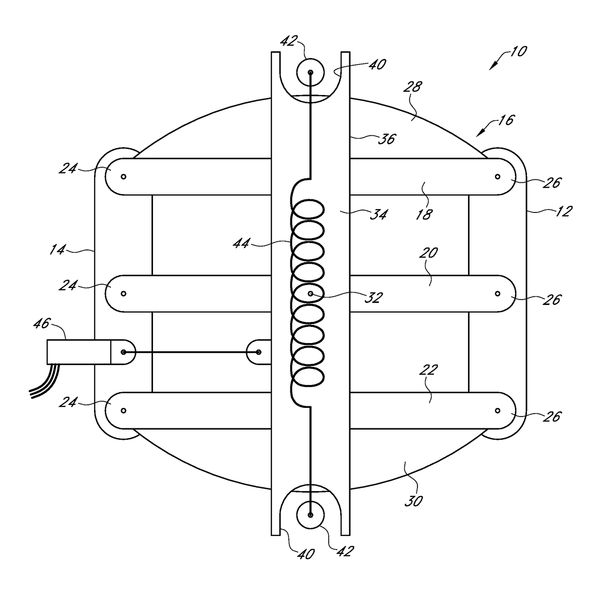
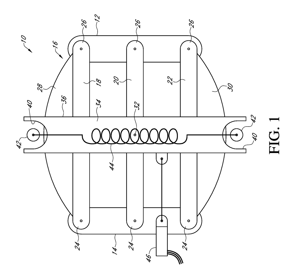
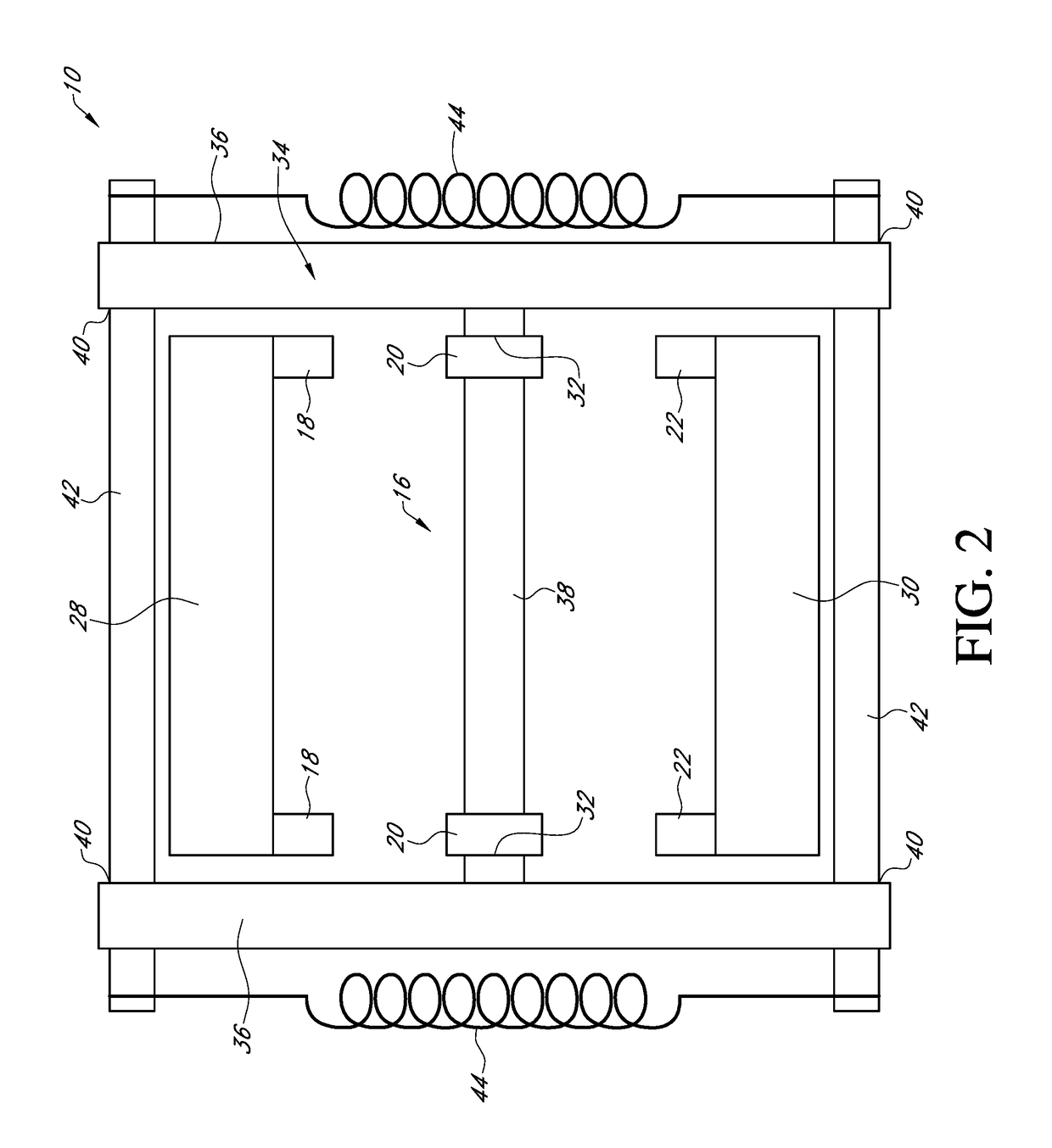
[0014]Referring to the figures, a downforce control assembly 10 connects a row unit 12 to a toolbar 14 of a planter by a six-bar linkage 16. The six-bar linkage 16 includes parallel top arms 18, parallel middle arms 20, and parallel bottom arms 22. A first end 24 of arms 18, 20, and 22 are pivotally connected to the toolbar 14 and a second end 26 of arms 18, 20, and 22 are pivotally connected to the row unit 12.

[0015]Added to a top surface of the top arms 18 is an arcuate member 28 that is convex in relation to the top arms 18. Added to the bottom surface of the bottom arms is an arcuate member 30 that is convex in relation to the bottom arms 22.

[0016]Pivotally connected to the middle arms 20 at pivot point 32 is a locator 34. Preferably, the locator 34 has an H-frame with generally vertical outer members 36 on a generally horizontal member 38 extending between the outer members 36. At opposite ends of the outer members 36 are slots 40 that preferably are arcuate in shape. The slots...


PUM


Abstract

A row unit downforce control assembly having a six bar linkage pivotally connected to a row unit and a tool bar. Pivotally connected to the six bar linkage is a locator. An actuator is connected to the locator and moves the locator to adjust downward force on the row unit.

Description

CROSS REFERENCE TO RELATED APPLICATION[0001]This application claims the benefit of U.S. Provisional Application No. 62 / 243,345 filed Oct. 19, 2015.BACKGROUND OF THE INVENTION[0002]This invention relates generally to agricultural equipment and more particularly to downforce adjustment of a row unit.[0003]Row units for planting seed are well-known in the art. Each row unit is mounted to a toolbar of a planter in a manner that allows each row unit to move vertically to adjust to the contour of the soil independently of other row units mounted to the tool bar.[0004]Various devices have been used to create a downforce on the row unit so that the row unit penetrates the soil and minimizes bounce in rough soil conditions. Inadequate downforce can result in shallow seed placement or seed placement on the soil surface. Too much downforce overly compacts the seed bed or forms a deep seed furrow that deters early plant development. Springs and airbags have been used to create downforce, but th...

Claims


Application Information

Patent Timeline
IPC IPC(8): A01C7/20A01B63/00
CPCA01C7/203A01B63/12A01B63/114A01B63/008A01C7/205
Inventor STRAETER, JAMES E.
Owner STRAETER JAMES E
Why Eureka
Try Eureka