Connecting-System Kit for a Respiratory Humidifier

a technology of connecting system and humidifier, which is applied in the direction of electrical and fluid coupling, medical devices, other medical devices, etc., can solve the problems of limiting the scope of design possibilities of respiratory humidifiers, affecting the appearance and practicality of respiratory humidifiers, and logical improvements in this regard are almost impossible to make with existing devices, so as to achieve the effect of reducing operating errors and flexibly being used

Active Publication Date: 2017-04-20
HAMILTON MEDICAL AG
View PDF3 Cites 2 Cited by
  • Summary
  • Abstract
  • Description
  • Claims
  • Application Information

AI Technical Summary

Benefits of technology

[0010]The connection system is characterized in that the electrical connection of the first contact element with the second contact element can be established in a second connecting direction different from the first connecting direction, preferably in a direction essentially perpendicular to the first connecting direction. This offers the advantage that the liquid container with the ventilation tube or with several ventilation tubes connected to it can be slid sideways, for example, into the housing of the respiratory humidifier, which thus facilitates a compact design for the respiratory humidifier.
[0011]It should be noted here that the tubing and connecting systems and the liquid containers for ventilators used in hospitals are frequently designed as single-use or disposable articles, and it is therefore logical to provide as many of the connections as possible on the single-use parts, so that the operating personnel are required to perform only a small number of connection procedures. As a result, the operating time is significantly reduced, and the risk of connecting the components improperly is minimized. In the situation present before the liquid container and the ventilation tube are connected together, the inventive connecting system offers the possibility of connecting the tube before or after the liquid container has been inserted into the housing of the respiratory humidifier. The lateral insertion of the liquid container / ventilation tube kit thus opens up the possibility of new and advantageous design alternatives.
[0019]It is especially advantageous that the first inhalation tube and the second inhalation tube can be connected by the use of either the first or the second connecting system, wherein the flow direction of the breathing gas can be recognized on the basis of the electrical contact elements. The respiratory humidifier can be thus be used flexibly, for it recognizes where the inhalation tube leading to the ventilator, i.e., to the source of the breathing air, is connected and then determines on this basis the direction in which the breathing air should flow through the respiratory humidifier. Operating errors by the user are thus further reduced, because reversing the connection of the inhalation tubes no longer leads to a malfunction.

Problems solved by technology

The disadvantage of the tube connecting system described in EP 1 369 141 A1 is that it can be placed onto the respiratory humidifier in only one direction, namely, from above.
Before the connection is made, the electrical contact elements on the housing project awkwardly from the housing as independent elements and thus interfere with the appearance and practicality of the respiratory humidifier.
Another disadvantage arising from this connecting system is that it limits the scope of possibilities for designing the respiratory humidifier.
Logical improvements in this regard are therefore almost impossible to make with the existing devices.

Method used


Image

  • Connecting-System Kit for a Respiratory Humidifier
  • Connecting-System Kit for a Respiratory Humidifier
  • Connecting-System Kit for a Respiratory Humidifier

Examples


Embodiment Construction

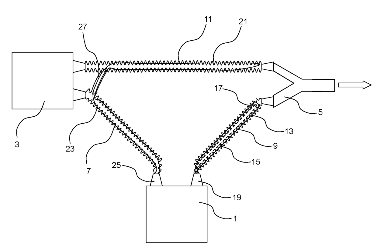
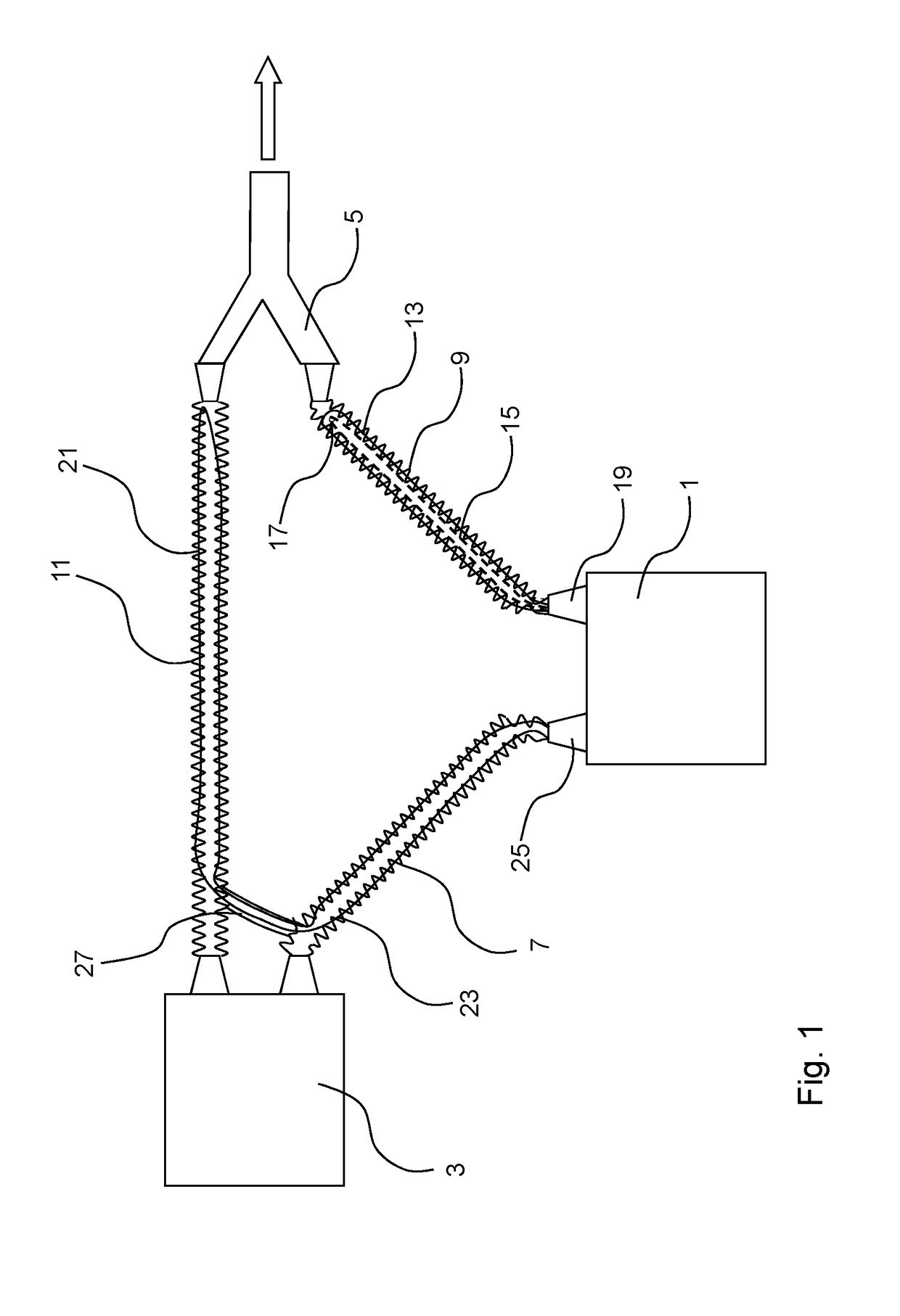
[0027]FIG. 1 schematically shows a preferred embodiment of a ventilation system having a connecting system according to the invention. A respiratory humidifier 1 is arranged between a respirator 3 and a Y-piece 5 and connected to them by a first inhalation or inspiration tube 7 and a second inhalation or inspiration tube 9. The simply designed end of the Y-piece 5 is pointing toward the patient to be ventilated, as indicated by the arrow. Finally, an exhalation or expiration tube 11 is arranged between the respirator 3 and the remaining end of the Y-piece 5.

[0028]A flow of dry breathing gas is produced by a blower (not shown), for example, in the respirator 3; this gas leaves the ventilator through the first inhalation tube 7 and proceeds toward the respiratory humidifier 1. There the breathing gas is conducted in the known manner into a liquid container (not shown in FIG. 1), where it is heated and humidified by the heated liquid. The heated and humidified breathing gas leaves the ...


PUM


Abstract

A liquid-container / ventilation-tube kit for a ventilation system that includes (a) a ventilator, (b) a respiratory humidifier having a housing and a liquid container, the housing having a pair of first electrical contact elements, (c) a first inhalation tube extending from the respiratory humidifier to a Y-piece, (d) a second inhalation tube extending from the ventilator to the respiratory humidifier, and (e) an exhalation tube extending from the Y-piece to the ventilator, the kit including the liquid container having a pair of first connection elements for removable connection of the first and second inhalation tubes thereto, and a pair of second connection elements each attached to a respective one of the first and second inhalation tubes and by which each of the inhalation tubes is pneumatically connected to a respective one of the first connection elements along a first connecting direction, each second connection element having a second electrical contact element that is positioned and arranged such that electrical connection with a respective one of the first electrical contact elements is possible in both of two ways, one when the pneumatic connection of the respective ventilation tube to the liquid container is effected after the liquid container has been inserted into the housing and the other when the liquid container is inserted into the housing after the pneumatic connection of the ventilation tubes to the liquid container has been effected.

Description

RELATED APPLICATIONS[0001]This is a continuation of Ser. No. 14 / 348,969, filed Apr. 1, 2014, which was based on PCT / EP2012 / 069125, filed Sep. 27, 2012, which claims priority to German Patent Application No. DE 10 2011 054 134.9, filed Oct. 1, 2011, the contents of which are incorporated by reference in their entireties.FIELD OF INVENTION[0002]The present invention relates to respiratory humidifiers for ventilation of patients with breathing gas, and more specifically to connecting systems for respiratory humidifiers.BACKGROUND OF THE INVENTION[0003]When patients are being mechanically ventilated on an intensive-care ward, for example, the patient to be ventilated is connected pneumatically to the ventilator or respirator by a system of ventilation tubing. Because the breathing gas supplied to the patient must be adjusted with respect to temperature and humidity to meet the physiological needs of the patient, a respiratory humidifier is arranged in the inhalation or inspiration tube ...

Claims


Application Information

Patent Timeline
Patent Type & Authority Applications(United States)
IPC IPC(8): A61M16/08A61M16/00A61M16/10A61M16/16
CPCA61M16/0833A61M16/16A61M16/0875A61M2205/3368A61M16/1095A61M16/0003A61M16/0057A61M16/022A61M16/0816A61M16/1075A61M2016/0036A61M2205/14A61M2205/3653H01R13/005
Inventor BUECHI, RUDOLFFREI, RETOMAEDER, MARCGRANZOTTO, THOMASZOLKOS, AXEL
Owner HAMILTON MEDICAL AG
Why Eureka
Try Eureka