
Ergonomic deadlift exercise bar

a deadlift and exercise bar technology, applied in the field of physical fitness, can solve the problems of deformation of vertebrae, low back pain, and often accompanying novices and athletes, and achieve the effects of preventing bowing, facilitating gripping of deadlift bars, and facilitating gripping

Active Publication Date: 2017-04-20
MANN ERIK C
View PDF3 Cites 20 Cited by
  • Summary
  • Abstract
  • Description
  • Claims
  • Application Information

AI Technical Summary

Benefits of technology

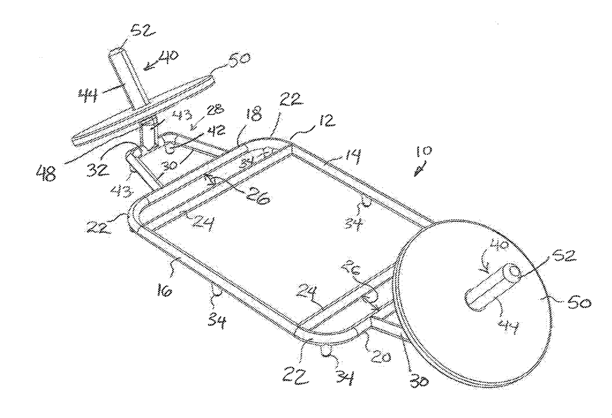
The present invention is a deadlift bar that is designed for better grip and comfort during use. The frame is made of rectangular members that are rigidly connected and has handles on the front and rear members. The handles can be covered with foam, plastic, or a knurled surface for a better grip. The frame also has legs spaced around it to make it easier to grip the bar when weights are on it. The bar has first and second platforms that are formed by protruding arms joined by a connecting member. The platforms also have legs to support the device and prevent bowing when weights are mounted on it. The bar has a support column that holds the weights and prevents them from sliding down or off the bar. The angled orientation of the support column helps to keep the weights in place even if the bar becomes tilts or uneven during use.

Problems solved by technology

One downside to the enjoyment of resistance training is the injuries that often accompany novices and athletes who fail to take heed of the need for proper alignment and technique.
One common ailment for weightlifters is low-back pain.
Heavy loads squeeze the intervertebral discs, leading to a deformation of the vertebrae and sometimes strained ligaments.
Deadlifting, an exercise that involves lifting a large weight using the large leg muscles, can lead to back injuries and muscle trauma if done improperly.
This is usually caused by the lifter bending over improperly, lifting with the back muscles instead of the leg muscles, placing undue strain on the lower back.

Method used


Image

  • Ergonomic deadlift exercise bar
  • Ergonomic deadlift exercise bar

Examples


Embodiment Construction

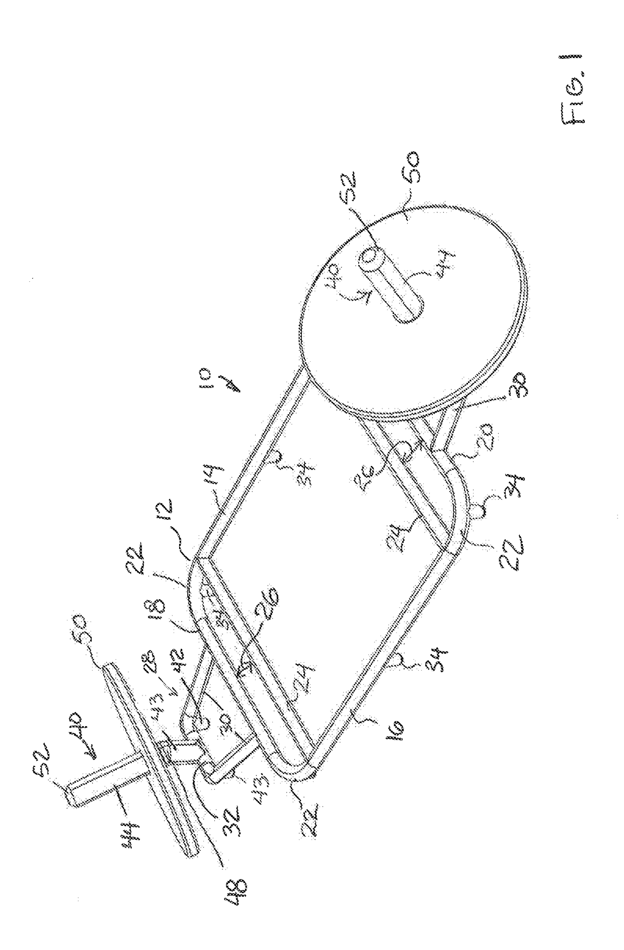
[0009]FIG. 1 illustrates a first preferred embodiment of the present invention. The invention is an exercise bar used in the practice of weightlifting, and more particularly deadlifting. A unique aspect of the present invention is that the user stands inside the frame of the bar and lifts the bar while the weight is centered about the user rather than lunging forward while lifting, preventing improper leaning during the lift that can lead to injuries.

[0010]The bar 10 includes a rectangular frame 12 formed by a front member 14, a rear member 16, a left member 18, and a right member 20. Rounded elbows 22 can be used to connect the adjacent members and form a closed rectangular arrangement. The members can be made of steel, or other suitable material of sufficient strength and durability to withstand the stresses of the loads placed on the bar 10. Similarly, the connections can be welded, threaded, or other suitable couplings that can reliably adjoin each element of the structure. The ...


PUM


Abstract

A deadlift bar includes a rectangular frame formed by front, rear, left, and right members. The frame includes a plurality of legs spaced about the frame to establish a gap between the frame and the ground, making it easier to grip the deadlift bar once the weights are loaded onto the device. Mounted to the left and right members and extending outwardly from the frame are first and second platforms, each of which may be formed by a pair of angled protruding arms joined at their respective ends by a connecting member. The platforms also include a pair of legs at the juncture of the arms with the connecting member to support the device and prevent bowing when weights are mounted thereon. Each platform further includes a support column extending upwardly from the connecting member, vertically at its base and then at an incline extending upwardly and away from the frame.

Description

CROSS-REFERENCES TO RELATED APPLICATIONS[0001]This application claims priority from U.S. Application Ser. No. 62 / 243,431, filed Oct. 19, 2015 incorporated by reference in its entirety.BACKGROUND[0002]In the field of physical fitness, resistance weight training is enjoying a growth in the number of participants and the along with the businesses that cater to this rapidly evolving training regiment. Resistance training (also called strength training or weight training) employs resistance to muscular contraction to build the strength, anaerobic endurance and size of skeletal muscles. Resistance training is based on the principle that muscles of the body will work to overcome a resistance force when they are required to do so.[0003]A growing body of research shows that working out with weights has health benefits beyond simply bulking up one's muscles and strengthening bones. Studies show that more lean muscle mass may allow kidney dialysis patients to live longer, give older people bet...

Claims


Application Information

Patent Timeline
Patent Type & Authority Applications(United States)
IPC IPC(8): A63B21/072A63B23/04A63B21/00
CPCA63B21/0724A63B2023/0411A63B23/0405A63B21/4035
Inventor MANN, ERIK C.
Owner MANN ERIK C
Learn More