
Screw member, fastening structure, and connection structure for solar panel float

a technology of solar panel and fastening structure, which is applied in the direction of screw, heat collector mounting/support, lighting and heating apparatus, etc., can solve the problem of burdening the operator, and achieve the effect of convenient fastening operation

Active Publication Date: 2017-04-20
KYORAKU CO LTD
View PDF23 Cites 7 Cited by
  • Summary
  • Abstract
  • Description
  • Claims
  • Application Information

AI Technical Summary

Benefits of technology

The invention provides a screw member, a fastening structure, and a connection structure for a solar panel float that make it easy to fasten using a screw.

Problems solved by technology

However, during such a fastening operation, an operator needs to rotate either of the bolt or the nut with a tool and the like while holding it by hand, which becomes burdensome to the operator.

Method used


Image

  • Screw member, fastening structure, and connection structure for solar panel float
  • Screw member, fastening structure, and connection structure for solar panel float
  • Screw member, fastening structure, and connection structure for solar panel float

Examples


second embodiment

Fastening Structure in Accordance with the Second Embodiment

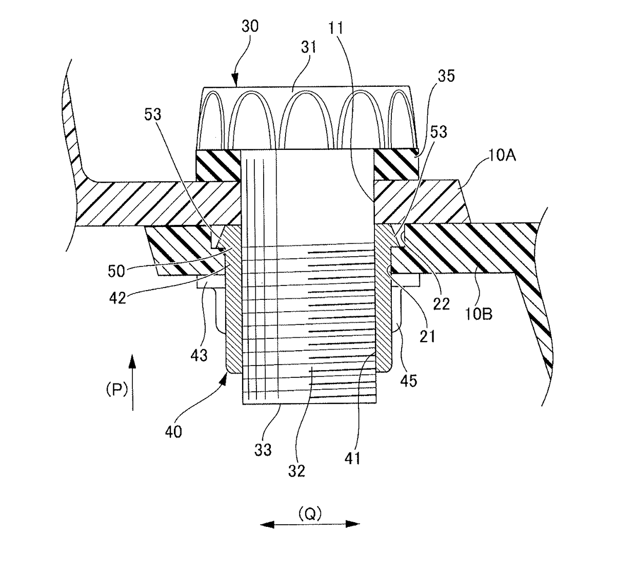
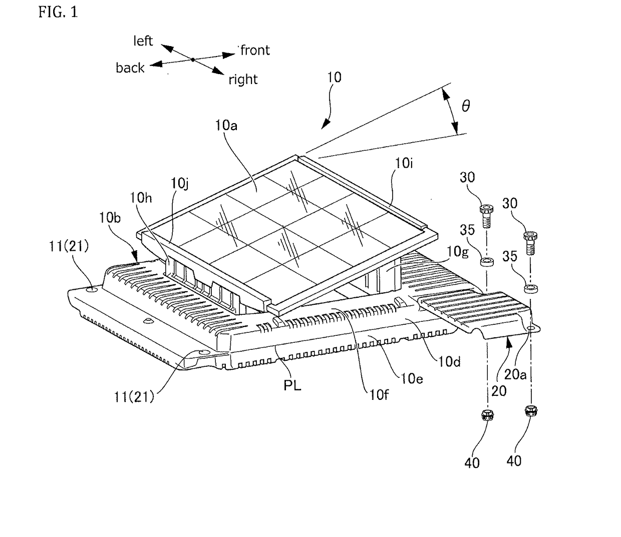
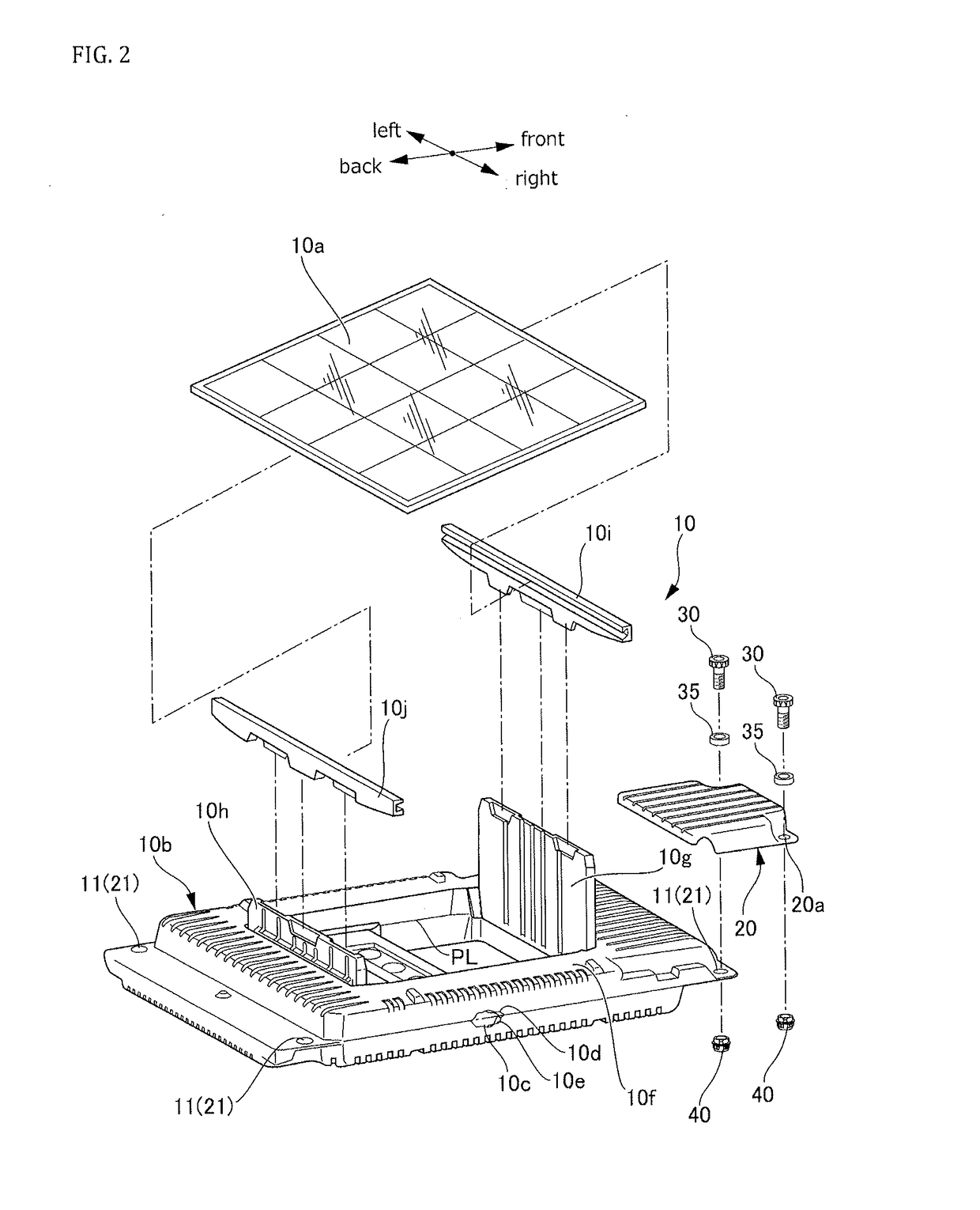
[0103]Next, a fastening structure in accordance with second embodiment will be hereinafter described with reference to FIGS. 12-21. As shown in FIGS. 12A and 12B, the fastening structure in accordance with the second embodiment is a connection structure for the solar panel float, and fastens the portion where the connection member 20 and the solar panel float 10A overlap. In this regard, the connection member 20 and the solar panel float 10A may constitute a plurality of objects to be fastened in accordance with the invention, and respectively correspond to the first object to be fastened and the second object to be fastened. The fastening structure has a third through-hole 20a provided in the connection member 20, the first though-hole 11 provided in the solar panel float 10A to match the third through-hole 20a, a female screw member 140, a male screw member 120, a bushing 35 which is provided between the connection member...

first embodiment

Modifications of First Embodiment

[0119]Next, the first to fifth modifications of the second embodiment will be hereinafter described with reference to FIGS. 22-26. As shown in FIG. 22, a fastening structure in accordance with the first modification of the second embodiment is basically similar to the fastening structure as shown in FIG. 12A except that a gap 151 is created between the bushing 35 and the female screw member 140.

[0120]As shown in FIG. 23, the fastening structure in accordance with the second modification of the second embodiment is basically similar to the fastening structure as shown in FIG. 12A except that the bushing 35 is omitted, and the seat surface portion 143 of the female screw member 140 is in direct contact with the connection member 20.

[0121]As shown in FIG. 24, the fastening structure in accordance with the third modification of the second embodiment is a connection structure for the solar panel float, and fastens the portion where three objects to be fas...


PUM


Abstract

A screw member, a fastening structure, and a connection structure for a solar panel float which can facilitate the fastening operation performed by a screw. A pair of screw members is provided with a male screw member and a female screw member. One of the male screw member and the female screw member has a body portion at least partly inserted into a through-hole provided in an object to be fastened, and a temporary fixing portion provided adjacent to an end of the body portion and locked in the object to be fastened so as to prevent the body portion from deviating from the through-hole during a fastening operation.

Description

TECHNICAL FIELD[0001]The invention relates to a screw member, a fastening structure and a connection structure for a solar panel float.BACKGROUND OF THE INVENTION[0002]Conventionally, various fastening techniques using a screw member have been proposed (e.g., Patent Document 1).[0003]Patent Document 1 discloses a bolt-and-nut fastening assembly for fastening two objected to be fastened by meshing the bolt with the nut. In general, if such a fastening assembly is used, the bolt meshes with the nut to sandwich the two objects to be fastened between a head portion of the bolt and a seat surface of the nut. As such, the two objects are fastened to each other.[0004]However, during such a fastening operation, an operator needs to rotate either of the bolt or the nut with a tool and the like while holding it by hand, which becomes burdensome to the operator.CITATION LISTPatent Literature[0005][Patent Document 1] Japanese Patent No. 4418025(B)SUMMARY OF THE INVENTION[0006]The invention has ...

Claims


Application Information

Patent Timeline
Patent Type & Authority Applications(United States)
IPC IPC(8): F16B41/00F16B37/04F24J2/52F16B35/04
CPCF16B41/002F16B35/041F24J2002/4692F24J2/526F24J2/5267F16B37/043Y02E10/47F24S25/11F24S20/70F24S25/65F24S2080/015Y02E10/50
Inventor YOSHIDA, KOHICHIROUMOTOHASHI, YOSHINORI
Owner KYORAKU CO LTD
Learn More