Board connector

a board connector and connector technology, applied in the direction of connection, electrical apparatus, coupling device connection, etc., can solve the problems of increasing the required insertion force, deformation of the leg, etc., and achieve the effect of increasing the locking margin, sufficient resilient displacement region of the leg, and enhancing the locking force of the leg to the circuit board

Active Publication Date: 2017-04-20
SUMITOMO WIRING SYST LTD
View PDF12 Cites 0 Cited by
  • Summary
  • Abstract
  • Description
  • Claims
  • Application Information

AI Technical Summary

Benefits of technology

[0008]The housing may include a tubular receptacle. The bottom surface may be configured as an outer surface of a bottom wall of the receptacle and the displacement allowing space may be a hole penetrating through the bottom wall of the receptacle. If the displacement allowing space is a bottomed recess open on the bottom surface of the bottom wall of the receptacle, only a depth of the recess can be ensured as the resilient displacement region of the base end side of the leg. In that respect, the displacement allowing space is a hole penetrating through the bottom wall of the receptacle so that a sufficient resilient displacement region of the leg can be ensured.
[0009]A pressed portion may be provided on an opening edge part of the displacement allowing space on an inner surface of the bottom wall of the receptacle and may be pressed by a mating connector fitted into the receptacle. The pressed portion is pressed by the mating connector. Thus, the leg is tilted and the locking portion can be displaced in a direction to increase a locking margin with the circuit board. Thus, a locking force of the leg to the circuit board can be enhanced.
[0010]Plural legs may be arranged via the displacement allowing space and an inserting member may be inserted into among the plurality of legs. The insertion of the inserting member among the plurality of legs restricts a resilient displacement of each leg. Thus, a locked state of the locks to the circuit board can be maintained stably.

Problems solved by technology

However, a larger engagement margin between the locks and the circuit board requires the legs to be deformed more when passing through the through holes and increase the required insertion force.

Method used


Image

  • Board connector
  • Board connector
  • Board connector

Examples


first embodiment

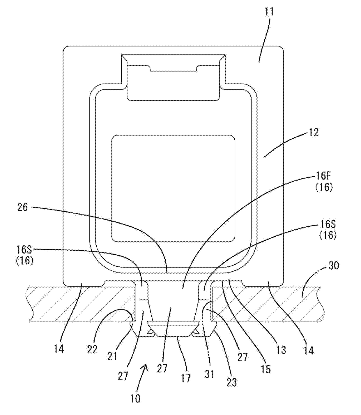
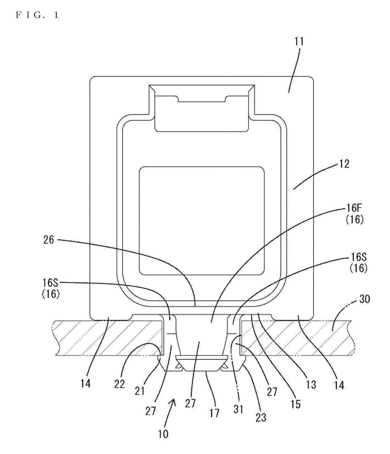
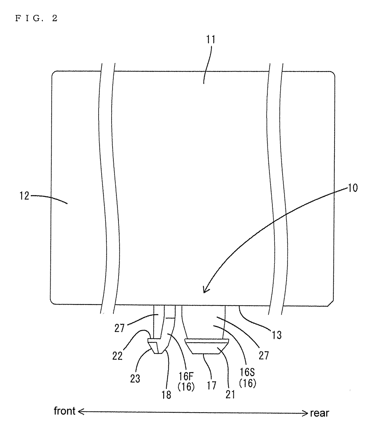
[0018]FIGS. 1 to 6 show a board connector that is to be mounted on a surface of a circuit board 30. The board connector includes a housing 11 that is provided integrally with a fixing portion 10 to be fixed by being inserted into a through hole 31 in the circuit board 30. The through hole 31 has a circular shape and penetrates through the circuit board 30 in a thickness direction. In the following description, a lower side and an upper side in FIG. 1 are referred to as a lower side and an upper side, and a left side and a right side in FIG. 2 are referred to as a front and a rear for each constituent member.

[0019]The housing 11 is made of synthetic resin and includes a receptacle 12 to be fit externally to a mating connector 40. The receptacle 12 is a substantially rectangular tube with a rectangular inner peripheral surface and the mating connector 40 can fit therein from the front. Unillustrated terminal fittings are held in the housing 11 and are to be connected electrically to t...

second embodiment

[0051]As described above, in the second embodiment, the inserting member 50 is inserted between the legs 16 to restrict a displacement of each leg 16. Thus, a state where the locks 21 are locked to the circuit board 30 can be maintained stably.

[0052]The invention is not limited to the above described and illustrated embodiments. For example, the following embodiments also are included in the scope of the invention.

[0053]Although the fixing portion 10 includes three legs 16 in the first and second embodiments, there is no limitation to this and only one, two, four or more leg portions may be provided.

[0054]Although the displacement allowing space 25 penetrates through the bottom wall 26 of the receptacle 12 in the vertical direction in the first and second embodiments, there is no limitation to this. For example, the displacement allowing space may be a bottomed recess formed by recessing the lower surface of the housing and having a closed upper side.

[0055]Although the shape of the ...


PUM


Abstract

A board connector has a housing (11) with legs (16) on a lower surface (13) facing a surface side of a circuit board (30). A locking portion (21) is provided on a tip end of the leg (16) and protrudes in a direction intersecting with a projecting direction from the lower surface (13) and can be locked to an underside of the circuit board (30). A base end of the leg portion (16) is defined by a displacement allowing space (25) recessed in from the lower surface (13) of the housing (11).

Description

BACKGROUND[0001]1. Field of the Invention[0002]The invention relates to a board connector.[0003]2. Description of the Related Art[0004]Japanese Unexamined Patent Publication No. H08-148241 relates to a board connector with a housing. Legs are cantilevered from the lower surface of the housing, and locks project from outer peripheral surfaces of the legs. The legs are inserted into through holes formed on a circuit board. The locks contact peripheral edge parts of the through holes as the legs are inserted into the through holes and this contact causes the legs to deform. The legs restore resiliently when the locks pass through the through holes, and the locks engage the underside of the circuit board to fix the board connector to the circuit board.[0005]Consideration has been given to making engagement margins between the locks and the circuit board larger to enhance a force for holding the circuit board. However, a larger engagement margin between the locks and the circuit board re...

Claims


Application Information

Patent Timeline
Patent Type & Authority Applications(United States)
IPC IPC(8): H01R12/70H01R12/71H01R12/73
CPCH01R12/7023H01R12/716H01R12/737
Inventor SAKAI, MASAMIISHIKAWA, YOSHIYUKI
Owner SUMITOMO WIRING SYST LTD
Why Eureka
Try Eureka