
Rotary oil seal of multi-head spiral oil return line

A technology of oil return line and spiral, which is applied in the direction of engine sealing, engine components, mechanical equipment, etc., can solve the problem that the sealing performance cannot be effectively guaranteed, and achieve the purpose of improving service life, improving oil return capacity, and strong oil return capacity Effect

Inactive Publication Date: 2010-05-05
YANTAI RUNFUXIANG OIL SEAL
View PDF0 Cites 11 Cited by
  • Summary
  • Abstract
  • Description
  • Claims
  • Application Information

AI Technical Summary

Problems solved by technology

[0002] At present, there are many application schemes for the design of PTFE (polytetrafluoroethylene) rotary oil seals. The lip design mainly adopts a single-head spiral oil return line, and its oil return capacity is determined by the shape and quantity of the spiral line. , due to its structure, from the failure analysis of the use process, oil leakage is still a basic performance, and the service life of the oil seal, that is, the sealing performance cannot be effectively guaranteed, which is mainly related to the design of the PTFE sealing lip. Especially closely related to the design of the lip line

Method used


Image

  • Rotary oil seal of multi-head spiral oil return line
  • Rotary oil seal of multi-head spiral oil return line
  • Rotary oil seal of multi-head spiral oil return line

Examples


Embodiment 1

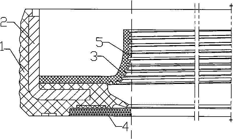
[0016] Example 1, a multi-head spiral oil return line rotary oil seal, refer to figure 1 , the rubber body 1 is bonded to the skeleton 2, the sealing lip 3 made of polytetrafluoroethylene sheet is bonded to the rubber body 1, the rubber body 1, the skeleton 2 and the sealing lip 3 are tightly combined into one, and the polytetrafluoroethylene There are 2-7 spiral oil return lines 5 on the side of the sealing lip 3 made of sheet and the shaft contact surface. The cross-sectional shape of the multi-head spiral oil return line 5 is rectangular, trapezoidal, triangular, semicircular arc or single-sided arc The distance between two adjacent oil return lines 5 is 0.3-1.2 mm, and the depth of the oil return lines 5 is 0.10-0.6 mm. In this embodiment, two oil return lines 5 with a trapezoidal section are used. , the distance between the two oil return lines 5 is 1.2mm, and the depth of the oil return line 5 is 0.6mm, which constitutes a structure of the present invention.

Embodiment 2

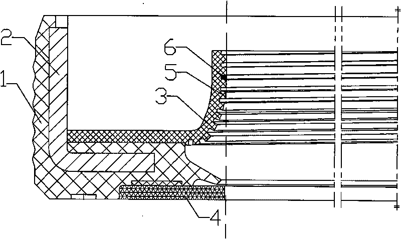
[0017] Example 2, a multi-head spiral oil return line rotary oil seal, refer to figure 2 , on the basis of Embodiment 1, an oil stop point 6 is provided on each spiral oil return line 5. In this embodiment, seven oil return lines 5 with triangular cross-sections are used, and the distance between two adjacent oil return lines 5 is Be 0.4mm, the depth 0.15mm of oil return line 5, others are identical with embodiment 1.

Embodiment 3

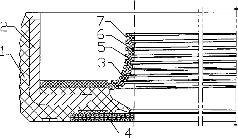
[0018] Example 3, a multi-head spiral oil return line rotary oil seal, refer to image 3 , on the basis of Example 2, on the opposite surface of the sealing lip 3 made of polytetrafluoroethylene sheets and the contact surface of the sealing shaft, there are helical lines 7 with the same number and the same direction of rotation as the 5 spiral oil return lines , the present embodiment adopts 4 oil return lines 5 with a semicircular cross-section, and there are 4 helical lines 7 correspondingly, the distance between two adjacent oil return lines 5 is 1.0 mm, the depth of the oil return line 5 is 0.35 mm, and other Exactly the same as Example 2.


PUM


Abstract

The invention discloses a rotary oil seal of a multi-head spiral oil return line, which comprises a rubber body, a skeleton and a seal lip. The rubber body, the skeleton and the seal lip are integrated, the seal lip is made from a polytetrafluoroethylene sheet, and the contact surface of the seal lip made from the polytetrafluoroethylene sheet and a shaft is provided with 2-7 spiral oil return lines of which the direction of rotation is in accordance with that of the shaft and intersected with the end of the polytetrafluoroethylene sheet for making the seal lip. By adopting the deign of multi-head helical line, the invention has the advantages of big oil return capability, reliable seal, long service life, energy conservation and environment protection, and is capable of preventing the entry of dust.

Description

technical field [0001] The invention belongs to the technical field of oil seals for rotary shafts, in particular to a polytetrafluoroethylene rotary oil seal used in environments with large changes in rotational speed. Background technique [0002] At present, there are many application schemes for the design of PTFE (polytetrafluoroethylene) rotary oil seals. The lip design mainly adopts a single-head spiral oil return line, and its oil return capacity is determined by the shape and quantity of the spiral line. , due to its structure, from the failure analysis of the use process, oil leakage is still a basic performance, and the service life of the oil seal, that is, the sealing performance cannot be effectively guaranteed, which is mainly related to the design of the PTFE sealing lip. Especially closely related to the design of the lip line. Contents of the invention [0003] The purpose of the present invention is to improve the deficiencies of the prior art and provi...

Claims


Application Information

Patent Timeline
Patent Type & Authority Applications(China)
IPC IPC(8): F16J15/32F16J15/3232F16J15/3248
Inventor 杜杰孙敢王晓英韩雪莲梁延忠初睿
Owner YANTAI RUNFUXIANG OIL SEAL
Learn More