Rotating electrical machine connection component and method of manufacturing the same

Active Publication Date: 2017-04-20
HITACHI METALS LTD +1
View PDF1 Cites 15 Cited by
  • Summary
  • Abstract
  • Description
  • Claims
  • Application Information

AI Technical Summary

Benefits of technology

The invention provides a component that connects two parts of a rotating electrical machine together. The component stops multiple conductors from moving in relation to a resin material where they are connected. This invention also has a method for manufacturing the connection component.

Problems solved by technology

If the fixing member of the connection component described in JP-A-2011-259654 is formed of a resin, the outer surface of the power lines frictionally slides on the inner surface of the through-holes due to vibration caused by motion of vehicle or rotation of the rotating electrical machine and the inner diameter of the through-holes may be enlarged due to the resulting wear of the fixing member.
Once the inner diameter of the through-holes is enlarged, the fixing member largely vibrates with respect to each power line and may generate noise.
If the inner diameter of the through-holes is enlarged due to wear of the fixing member in such a case, the power lines are not appropriately fixed to each other by the fixing member, a distance between the power lines or a distance between the power line and the winding may be reduced due to the relative movement of the power lines with respect to the fixing member, so that the insulation distance may not be secured sufficiently.

Method used


Image

  • Rotating electrical machine connection component and method of manufacturing the same
  • Rotating electrical machine connection component and method of manufacturing the same
  • Rotating electrical machine connection component and method of manufacturing the same

Examples


embodiment

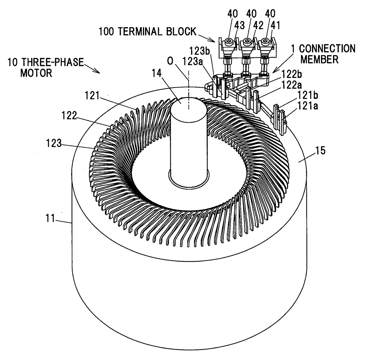
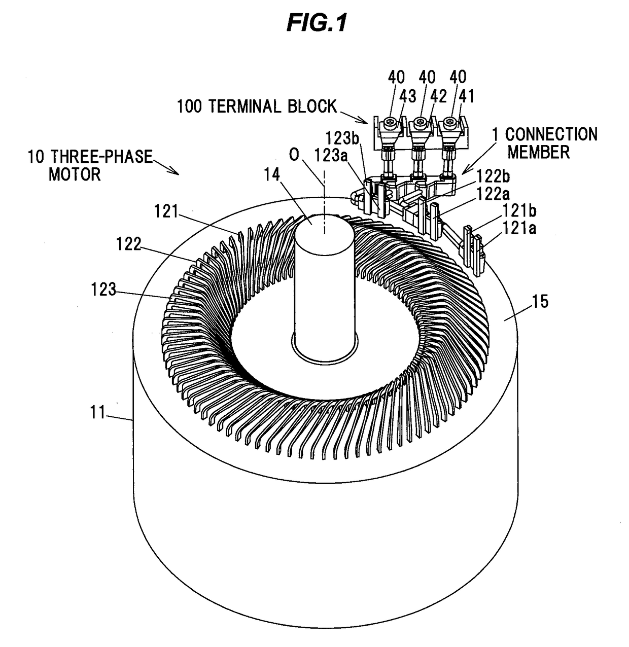
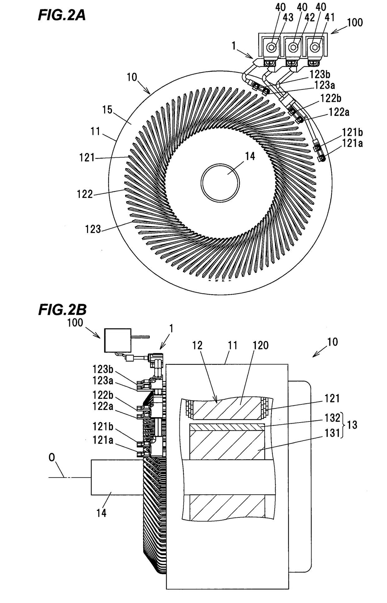
[0028]FIG. 1 is a perspective view showing a rotating electrical machine connection component 1 in an embodiment of the invention and a three-phase motor 10 as a rotating electrical machine which is supplied with an electric current through the rotating electrical machine connection component 1. FIG. 2A is a plan view showing the rotating electrical machine connection component 1 and the three-phase motor 10 and FIG. 2B is a side view showing the rotating electrical machine connection component 1 and the three-phase motor 10. In FIG. 2B, a portion of the three-phase motor 10 is cutaway to show the internal structure.

[0029]The three-phase motor 10 is mounted as a drive source on a vehicle and is supplied with three-phase AC currents from an inverted (not shown) via a terminal block 100 and the rotating electrical machine connection component 1. Hereinafter, the rotating electrical machine connection component 1 is simply referred as “connection component 1”.

[0030]The three-phase moto...


PUM


Abstract

A rotating electrical machine connection component includes a plurality of linear conductors, and a first molded resin portion that covers portions of the plurality of linear conductors and connects the plurality of linear conductors to each other. Each of the plurality of linear conductors includes a first straight portion extending out of the first molded resin portion in a direction parallel to a rotational axis of the rotor and connected to the terminal block, a second straight portion extending out of the first molded resin portion in a different direction from the first straight portion and a bent portion bent between the first and second straight portions. Of each of the plurality of linear conductors, a part of the first straight portion, the bend portion and a part of the second straight portion are covered by the first molded resin portion.

Description

[0001]The present application is based on Japanese patent application No. 2015-206093 filed on Oct. 20, 2015, the entire contents of which are incorporated herein by reference.BACKGROUND OF THE INVENTION[0002]1. Field of the Invention[0003]The invention relates to a rotating electrical machine connection component used to supply multi-phase currents having different phases to windings of a stator of a rotating electrical machine, and a method of manufacturing the rotating electrical machine connection component.[0004]2. Description of the Related Art[0005]A rotating electrical machine is mounted as a drive source on electric cars and so-called hybrid vehicles. A rotating electrical machine has a rotor with a permanent magnet fixed to a circumferential surface and a stator composed of an annular core surrounding the rotor and windings wound thereon. The rotating electrical machine may be provided with a terminal block which is arranged in the vicinity thereof and through which multi-...

Claims


Application Information

Patent Timeline
IPC IPC(8): H02K5/22H02K15/00
CPCH02K5/225H02K15/0068H02K15/0062H02K3/50
Inventor EGAMI, KENICHIYOSHIZAWA, TAKUYAOKAMURA, MITSUHIRO
Owner HITACHI METALS LTD
Why Eureka
Try Eureka