Tourniquet and methods of use and construction thereof

a technology of tourniquets and rigid parts, applied in the field of tourniquets, can solve the problems of occupying as much space as the rigid member(s) need, affecting the use, and affecting the safety of the rigid member, etc., and achieves the effect of being readily availabl

Active Publication Date: 2017-04-27
BROWN ALICE M
View PDF5 Cites 3 Cited by
  • Summary
  • Abstract
  • Description
  • Claims
  • Application Information

AI Technical Summary

Benefits of technology

[0018]In accordance with another aspect of the invention, a method of occluding the flow of blood in an injured limb is provided. The method includes wrapping a strap of inelastic material about an injured limb suffering blood loss from a serious wound and reverse folding a portion of the strap through an annulus. Then, extending a fastener assembly from the strap and fixing a first fastener portion of the fastener assembly to an outwardly facing side of the strap, wherein the first fastener portion is readily releasable from the side of the strap to allow adjustment of the constriction force applied by the strap about the injured limb. Then, ensuring the flow of the blood from the injured limb is stopped or substantially stopped.
[0019]Further, fixing a second fastener portion of the

Problems solved by technology

Although these types of items can prove useful, they can be unreliable if not applied in just the right manner, and further, can become inadvertently loosened or in some cases removed, such as by the injured person when experiencing pain, sometimes as a result of the tourniquet itself cutting off blood flow, thereby allowing the bleeding to continue.
Although useful, they can prove difficult to apply properly, and thus, can lead to improper use, particularly by those that lack the proper training and certification.
In addition, many known tourniquets are relatively expensiv

Method used


Image

  • Tourniquet and methods of use and construction thereof
  • Tourniquet and methods of use and construction thereof
  • Tourniquet and methods of use and construction thereof

Examples


Embodiment Construction

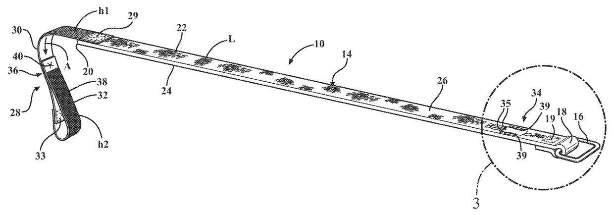
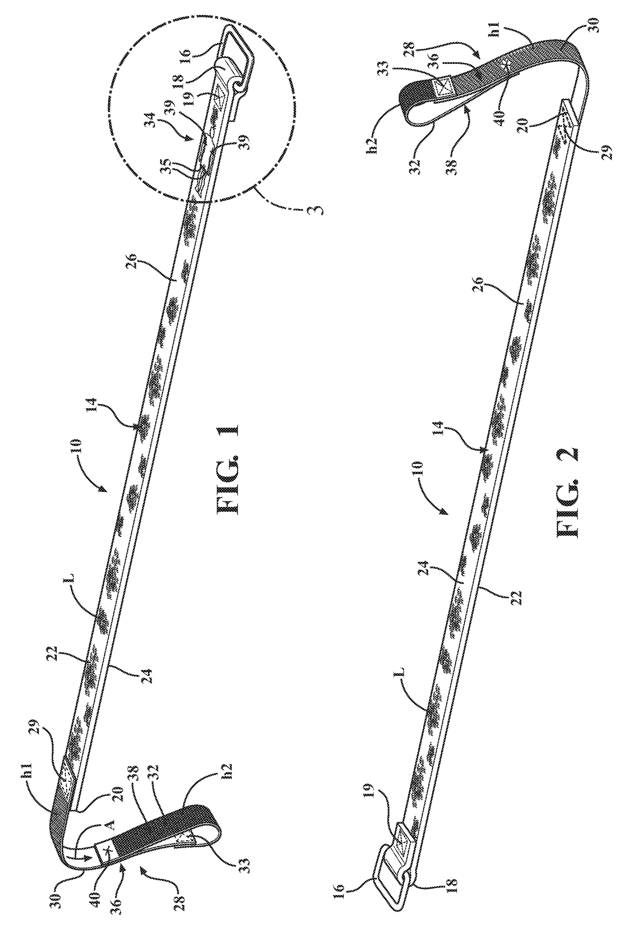
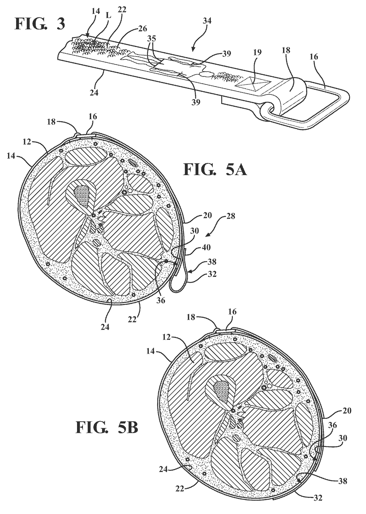
[0041]Referring in more detail to the drawings, FIGS. 1, 2 and 4 illustrate a tourniquet 10, constructed in accordance with one aspect of the invention, for occluding the flow of blood in an injured limb 12. The tourniquet 10 includes a strap 14 of flexible, highly inelastic material having an annulus 16, such as a closed or substantially closed loop of metal or polymeric material fixed at a first end18, such as via a stitching 19 or otherwise, as desired, and having an opposite second end 20 extendible through the annulus 16 to enable the strap 14 to be wrapped about the injured limb 12 in need of a tourniquet. The strap 14 has opposite sides 22, 24 with at least one side, and preferably both sides 22, 24 having a hook or loop fastener portion, constructed as a loop fastener portion 26, having a plurality of loops (L), in a preferred embodiment. A fastener assembly 28 is fixed to the second end 20 of the strap 14, such as via a stitching 29 or otherwise, as desired. The fastener as...


PUM


Abstract

A tourniquet for occluding the flow of blood in an injured limb, and methods of use and construction thereof is provided. The tourniquet includes a strap of inelastic material having an annulus at a first end and a fastener assembly a second end. The fastener assembly is extendible through the annulus, and the strap has a hook or loop fastener portion on at least one side. The fastener assembly includes first and second fastener portions. The first fastener portion is releasably fixable to the hook or loop fastener portion on the strap and is separable from the hook or loop fastener portion under a first tensile force. The second fastener portion is fixable to the hook or loop fastener portion on the strap and is separable from the hook or loop fastener portion under a second tensile force, wherein the second tensile force is greater than the first tensile force.

Description

CROSS-REFERENCE TO RELATED APPLICATION[0001]This application claims the benefit of U.S. Provisional Application Ser. No. 62 / 246,865, filed Oct. 27, 2015, which is incorporated herein by reference in its entirety.BACKGROUND OF THE INVENTION[0002]1. Technical Field[0003]This invention relates generally to devices for impeding the flow of blood in a body, and more particularly to tourniquets and to their methods of use and construction.[0004]2. Related Art[0005]Tourniquets are sometimes used in emergency and / or combat situations as a device to stop severe bleeding of limb of a badly injured person, such as a combat soldier or someone who has suffered a gunshot wound, a severe laceration or internal bleeding. In many cases, where a dedicated tourniquet is not readily available, a belt, shirt, shoe lace, handkerchief or similar device is often used by wrapping the item about the circumference of the injured limb at a location above the wound and is tightened, often with the aid of a stic...

Claims


Application Information

Patent Timeline
IPC IPC(8): A61B17/132
CPCA61B17/1327A61B17/1322A61B2090/0807
Inventor BROWN, ALICE M.
Owner BROWN ALICE M
Why Eureka
Try Eureka