Heterostructure device

a technology of heterostructure and transistor, applied in the direction of semiconductor devices, basic electric elements, electrical appliances, etc., can solve the problem of component performance bottleneck in energy conversion efficiency, and achieve the effect of cost reduction

Active Publication Date: 2017-04-27
EPISTAR CORP
View PDF15 Cites 11 Cited by
  • Summary
  • Abstract
  • Description
  • Claims
  • Application Information

AI Technical Summary

Benefits of technology

[0009]An object of the present invention is to provide a HFET using a p-type group IIIA-VA material for forming a depletion region, so that reverse blocking capability can also be achieved.
[0012]Another object of the present invention is to provide advantages over conventional HFET devices which include the following: providing capability of having just one single process to perform to form a Schottky-ohmic drain contact, thereby achieving cost reductions, using the p-type group IIIA-VA material for forming the depletion region, so that reverse blocking capability is achieved.
[0016]To achieve one or more of the objects, in addition, a second method for fabricating a HFET device of the embodiment of present invention including the following steps is provided: first, a buffer layer, a channel layer, a barrier layer, and a p-GaN layer or a p-AlGaN layer are respectively grown by metal organic chemical-vapor deposition (MOCVD) on a substrate in sequential order; second, a mask layer is formed and patterned by etching thereof on the p-GaN layer or the p-AlGaN layer; third, using the patterned mask layer, a p-GaN patterned structure or a p-AlGaN patterned structure is formed by dry-etching the p-GaN layer or the p-AlGaN layer by inductively coupled plasma (ICP) on the barrier layer; fourth, the source and drain contacts / electrodes, comprising of a same material, are formed at the same time, with the source ohmic contact formed on the barrier layer, the drain Schottky contact formed on the p-GaN / p-AlGaN patterned structure and the drain ohmic contact formed on the AlGaN barrier layer, respectively; fifth, a Schottky gate is formed on the AlGaN barrier layer to form the HFET device. The HFET fabricated by each of the above fabrication methods possesses improved forward OFF-state blocking performance and a reverse blocking capability, and better protected from a reverse-battery connection, such as when used as a power switch in electric vehicles, or from damage due to inadvertent biasing drain terminal and a negative bias voltage so as to achieve better device longevity. Meanwhile, the Schottky-ohmic drain for the HFET is fabricated using one processing step so as to lower fabrication cost without sacrificing forward OFF-state blocking performance.
[0019]Advantages of present invention include the following: having capability of performing just one single process to form a Schottky-ohmic drain contact, thereby achieving cost reduction, using the p-type group IIIA-VA material for forming the depletion region, so reverse blocking capability is also achieved.

Problems solved by technology

Most conventional power components are based on Si-based materials, because Si material is relatively inexpensive and is considered a well-understood material, but due to the limitations of the physical properties of the Si material, its role as a power component has reached a performance bottleneck in energy conversion efficiency.

Method used


Image

  • Heterostructure device
  • Heterostructure device
  • Heterostructure device

Examples


Embodiment Construction

[0032]The present invention will now be described more specifically with reference to the following embodiments. It is to be noted that the following descriptions of the embodiments of this invention are presented herein for purpose of illustration and description only. It is not intended to be exhaustive or to be limited to the precise form disclosed.

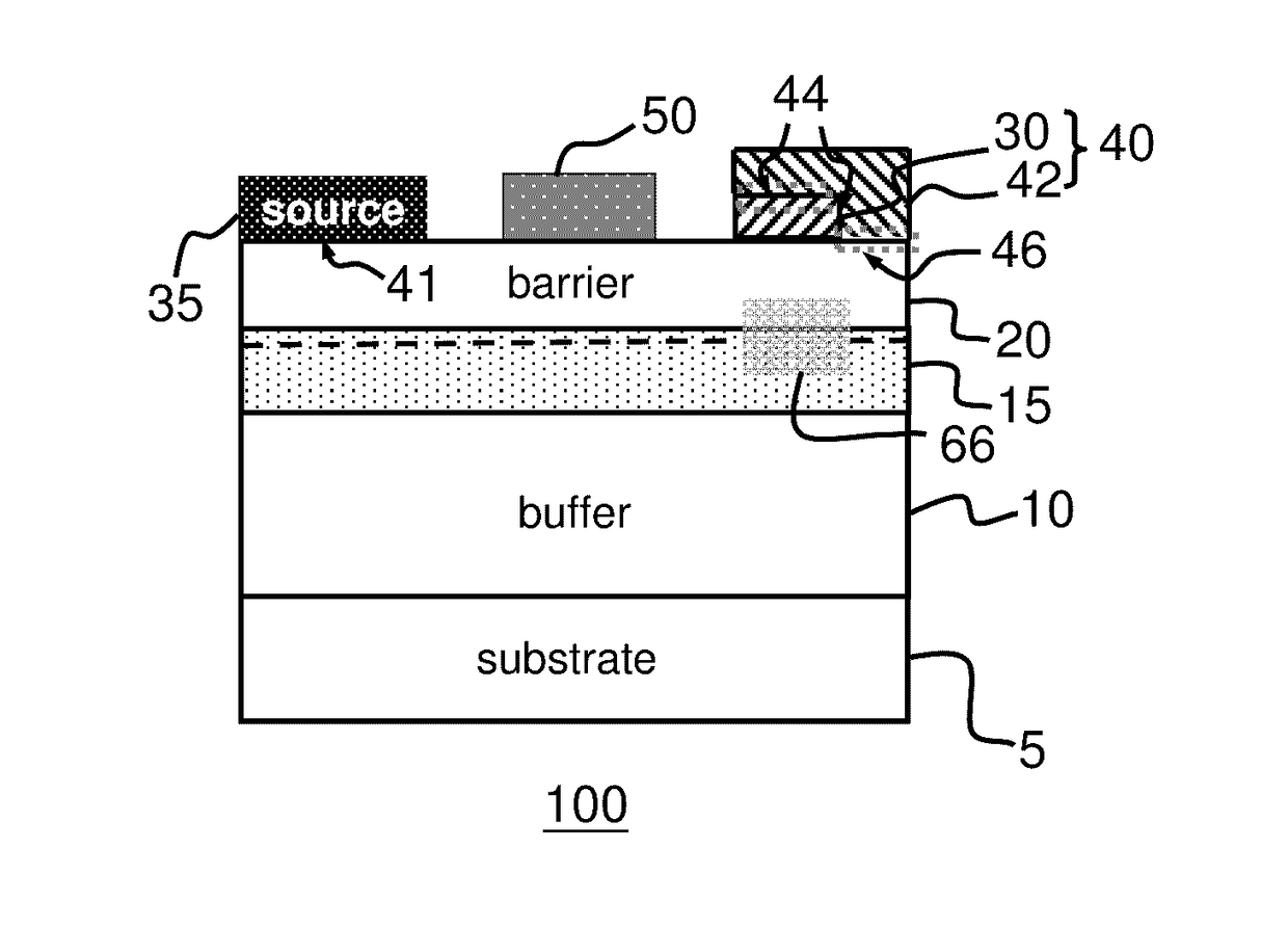
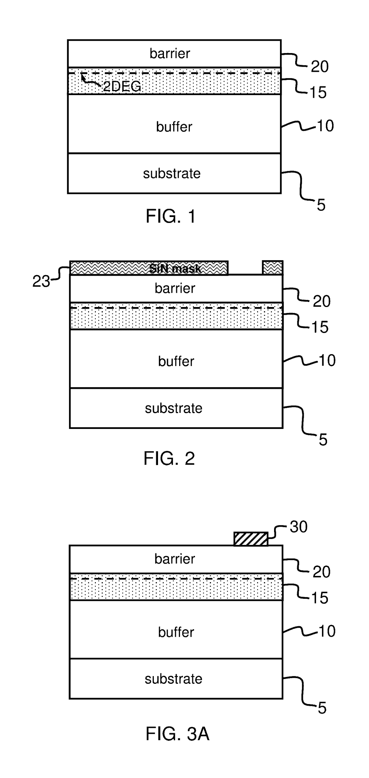
[0033]Referring to FIGS. 1-5, a first method for fabricating a heterostructure field effect transistor (HFET) device 100 according to an embodiment of present invention includes the following steps: in a first step, a buffer layer 10, a channel layer 15 including a first group IIIA-VA semiconductor material, and an barrier layer 20 including a first group IIIA-VA semiconductor material are respectively epitaxially grown by metal organic chemical-vapor deposition (MOCVD), hydride vapor phase epitaxy (HVPE), liquid phase epitaxy (LPE), and so forth on a substrate 5 in sequential order as shown in FIG. 1. A two-dimensional electron gas (2...


PUM

PropertyMeasurementUnit
drain-source voltageaaaaaaaaaa
p-type semiconductoraaaaaaaaaa
widthaaaaaaaaaa

Abstract

A heterostructure device includes a channel layer, a barrier layer disposed on the channel layer, and a first electrode and a second electrode disposed on the barrier layer, respectively. The second electrode includes a p-type semiconductor structure and a raised section disposed on the p-type semiconductor structure, the second electrode includes a Schottky contact and an ohmic contact, the Schottky contact is formed between a top surface of the p-type semiconductor structure and a first bottom surface of the raised section, the ohmic contact is formed between a second bottom surface of the raised section and the barrier layer.

Description

REFERENCE TO RELATED APPLICATION[0001]This application is a continuation application of U.S. patent application Ser. No. 14 / 864,680, filed on Sep. 24, 2015, now pending, and the content of which is hereby incorporated by reference in its entirety.BACKGROUND OF THE INVENTION[0002](a) Field of the Invention[0003]The present invention is related to a heterostructure field effect transistor (HFET), and more particularly, to a group IIIA-VA HFET and method of fabricating the same.[0004](b) Description of the Prior Art[0005]Today Schottky barrier diodes are used in many power switching applications such as switch mode power supplies (SMPS), converters, and inverters. Engineers and scientists have used heterostructure FET (HFET) or high-electron-mobility transistor (HEMT) to create Schottky barrier diodes. A heterostructure FET (HFET) or a high-electron-mobility transistor (HEMT) is a field-effect transistor (FET) incorporating a junction between two materials with different band gaps (i.e...

Claims


Application Information

Patent Timeline
Patent Type & Authority Applications(United States)
IPC IPC(8): H01L29/47H01L21/285H01L29/20H01L29/205H01L29/778H01L29/417
CPCH01L29/475H01L29/7786H01L29/41725H01L21/28593H01L29/2003H01L29/205H01L21/28581H01L29/41758H01L29/0619H01L29/66462H01L21/283H01L21/30612
Inventor YANG, YA-YULIN, PING-HAO
Owner EPISTAR CORP
Why Eureka
Try Eureka