Glare suppression through fog by optical phase conjugation assisted active cancellation

a phase conjugation and active cancellation technology, applied in the field of suppressing glare, can solve the problems of destructive interference of reference radiation with backscattered radiation on one or more sensor pixels, and achieve the effect of suppressing glare and reducing the impact on viewer ability

Active Publication Date: 2017-04-27
CALIFORNIA INST OF TECH
View PDF0 Cites 52 Cited by
  • Summary
  • Abstract
  • Description
  • Claims
  • Application Information

AI Technical Summary

Benefits of technology

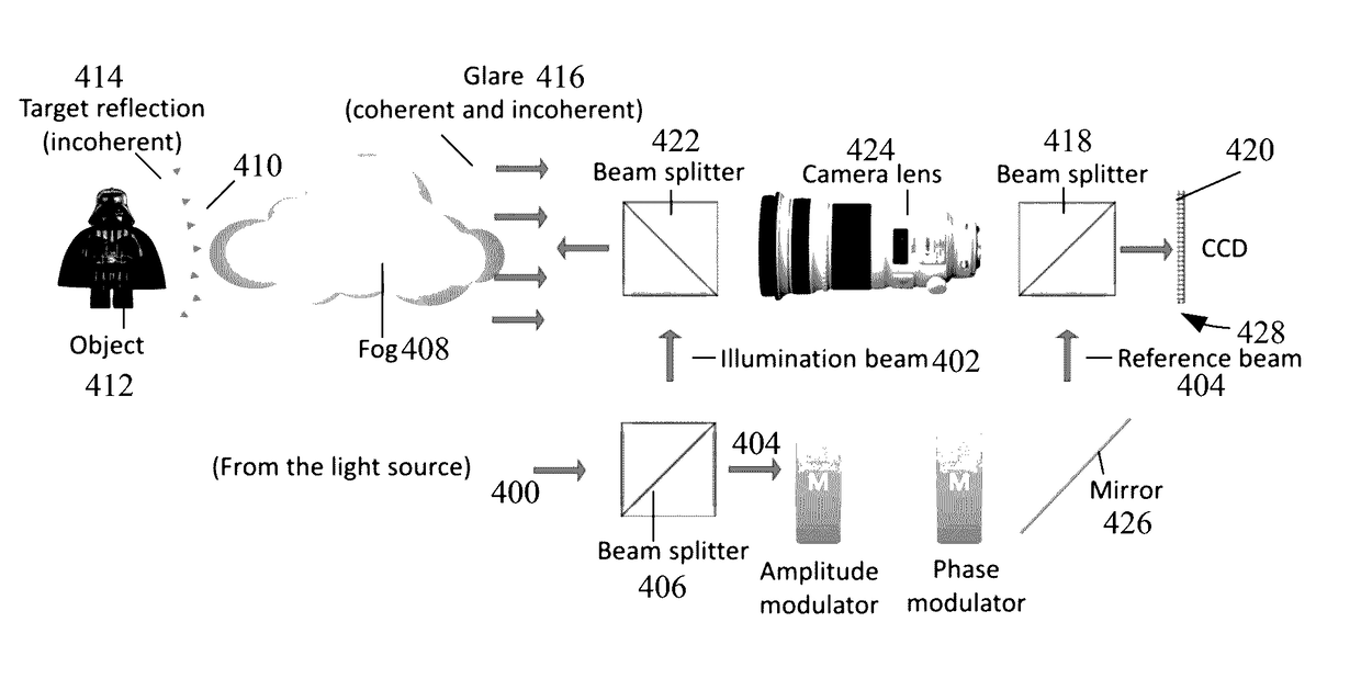
[0023]One or more embodiments of the present invention describe a simpler solution to the problem of trying to see through a scattering medium (such as fog or water vapor), by identifying that the major limitation to seeing through the scattering medium is often the glare created by the illumination of the scattering medium from the vantage point of the viewer. The present invention suppresses the glare, so that the scattering medium has a much smaller impact on the ability of the viewer to see objects in the scattering medium.

Problems solved by technology

The reference radiation destructively interferes with the backscattered radiation on the one or more sensor pixels while the object is imaged on the one or more sensor pixels using the imaging radiation.

Method used


Image

  • Glare suppression through fog by optical phase conjugation assisted active cancellation
  • Glare suppression through fog by optical phase conjugation assisted active cancellation
  • Glare suppression through fog by optical phase conjugation assisted active cancellation

Examples


Embodiment Construction

[0054]In the following description of the preferred embodiment, reference is made to the accompanying drawings which form a part hereof, and in which is shown by way of illustration a specific embodiment in which the invention may be practiced. It is to be understood that other embodiments may be utilized and structural changes may be made without departing from the scope of the present invention.

[0055]Technical Description

[0056]Overview

[0057]The scattering nature of fog, sandstorms, and rain confound our ability to image objects within the medium. There are two major confounding factors in this imaging scenario. The first confounding factor has to do with the fact that scattering randomizes the light ray trajectories and effectively introduces a blur to the image [31]. In an anisotropically scattering medium, this blurring effect scales as a function of the reduced scattering coefficient. Practically, for macroscale objects such as a vehicle, this blurring effect is not necessarily...


PUM


Abstract

A method of imaging an object on one or more sensor pixels and with reduced glare. The method includes irradiating a scattering medium and the object behind the scattering medium, creating backscattered radiation and imaging radiation that are received on the one or more pixels. The method includes digitally adjusting a phase, an amplitude, or a phase and amplitude, of reference radiation transmitted onto the one or more sensor pixels, wherein the reference radiation destructively interferes with the backscattered radiation (glare) on the one or more sensor pixels while the object is imaged on the one or more sensor pixels using the imaging radiation.

Description

CROSS REFERENCE TO RELATED APPLICATIONS[0001]This application claims the benefit under 35 U.S.C. Section 119(e) of co-pending and commonly-assigned U.S. applications:[0002]U.S. Provisional Patent Application No. 62 / 245,847, filed Oct. 23, 2015, by Edward H. Zhou, Joshua Brake, and Changhuei Yang, entitled “FOG GLARE SUPPRESSION BY COHERENCE GATING NEGATION,” (CIT-7338-P); and[0003]U.S. Provisional Patent Application No. 62 / 245,843, filed Oct. 23, 2015, by Edward H. Zhou, Joshua Brake, and Changhuei Yang, entitled “GLARE SUPPRESSION THROUGH FOG BY OPTICAL PHASE CONJUGATION ASSISTED ACTIVE CANCELLATION,” (CIT-7337-P);[0004]which applications are incorporated by reference herein.[0005]This application is related to the following co-pending and commonly-assigned patent applications, which applications are incorporated by reference herein:[0006]U.S. Utility patent application Ser. No. 15 / 181,160 filed on Jun. 13, 2016, by Haowen Ruan, Mooseok Jang, Changhuei Yang, and Daifa Wang, entitle...

Claims


Application Information

Patent Timeline
Patent Type & Authority Applications(United States)
IPC IPC(8): H04N5/357G02B27/00G02B27/10H04N5/225G02B26/06
CPCH04N5/357H04N5/2254G02B27/0068G02B27/1066G02B26/06H04N23/74H04N25/60
Inventor ZHOU, EDWARD H.BRAKE, JOSHUAYANG, CHANGHUEI
Owner CALIFORNIA INST OF TECH
Why Eureka
Try Eureka