Electrohydraulic drawing press cushion drive

a technology of electric hydraulic pump and cushion drive, which is applied in the direction of fluid couplings, couplings, manufacturing tools, etc., can solve the problems of power loss in force generating devices in the area of 100 kw or even more, correspondingly large amount of energy provided by the drawing cushion, etc., and achieve high control dynamics, high energy loss, and high control dynamic

Inactive Publication Date: 2008-06-19
SCHULER PRESSEN GMBH & CO KG
View PDF6 Cites 31 Cited by
  • Summary
  • Abstract
  • Description
  • Claims
  • Application Information

AI Technical Summary

Benefits of technology

[0014]Although conventional hydraulic drawing cushions have high energy losses, they have high control dynamics. That is, the drawing forces can be changed very rapidly simply by adjustment of the throttle valves. In mechanical servo-drives of drawing cushions, such high dynamics can not be achieved because of the necessary acceleration and deceleration of the service motors. They, however, permit an energy recuperation. The concept according to the present invention combines the advantages of both solutions in that, on one hand, at least if additional control valves are provided in the hydraulic circuit, the high control dynamics of conventional drawing cushions can be achieved and, on the other hand, energy recuperation is possible.
[0015]Furthermore, any play between the drawing cushion and the electric motor is omitted. If, for example, the drawing cushion is to be pre-accelerated in the plunger direction shortly before the plunger or, respectively, top tool part contacts the sheet metal to be deformed, in order to cause engagement of the top tool part with the sheet metal with only a relatively small impact, the electric motor has a drive function. As soon as the top tool part comes in contact with the sheet metal, it begins to push the drawing cushion downwardly. The electric motor reverses its direction of rotation. It operates now as a generator and brakes the drawing cushion. With the torque reversal, no plays are encountered as it is the case, for example, with spindle drives. This substantially improves the mechanical behavior and the controllability of the drive arrangement.

Problems solved by technology

Since, under such circumstances, the force required to hold the metal sheet in place, a correspondingly large amount of energy must be provided by the drawing cushion.
With the common press operating speeds with drawing cushions or, respectively, the force generating means, power losses may occur in force generating devices in the area of 100 KW or even more.

Method used


Image

  • Electrohydraulic drawing press cushion drive
  • Electrohydraulic drawing press cushion drive
  • Electrohydraulic drawing press cushion drive

Examples


Embodiment Construction

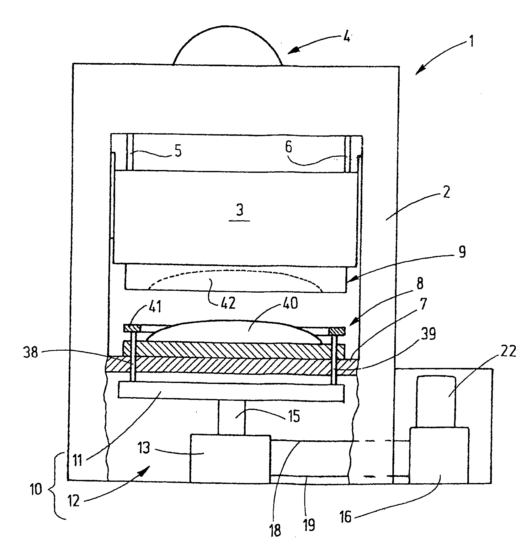
[0022]FIG. 1 shows schematically a press 1. It includes a press frame 2 with a plunger 3 preferably vertically movably supported thereby. The plunger 3 provided with, as shown in the embodiment, conventional main press drive 4 which drives the plunger 3, for example via a mechanical drive which is not shown in detail, but which includes an eccentric member and a crank 5, 6.

[0023]Opposite the plunger 3, in this case below the plunger 3, a press table 7 is arranged on which the bottom tool part 8 is disposed. The plunger 3 curves the respective top tool part 9.

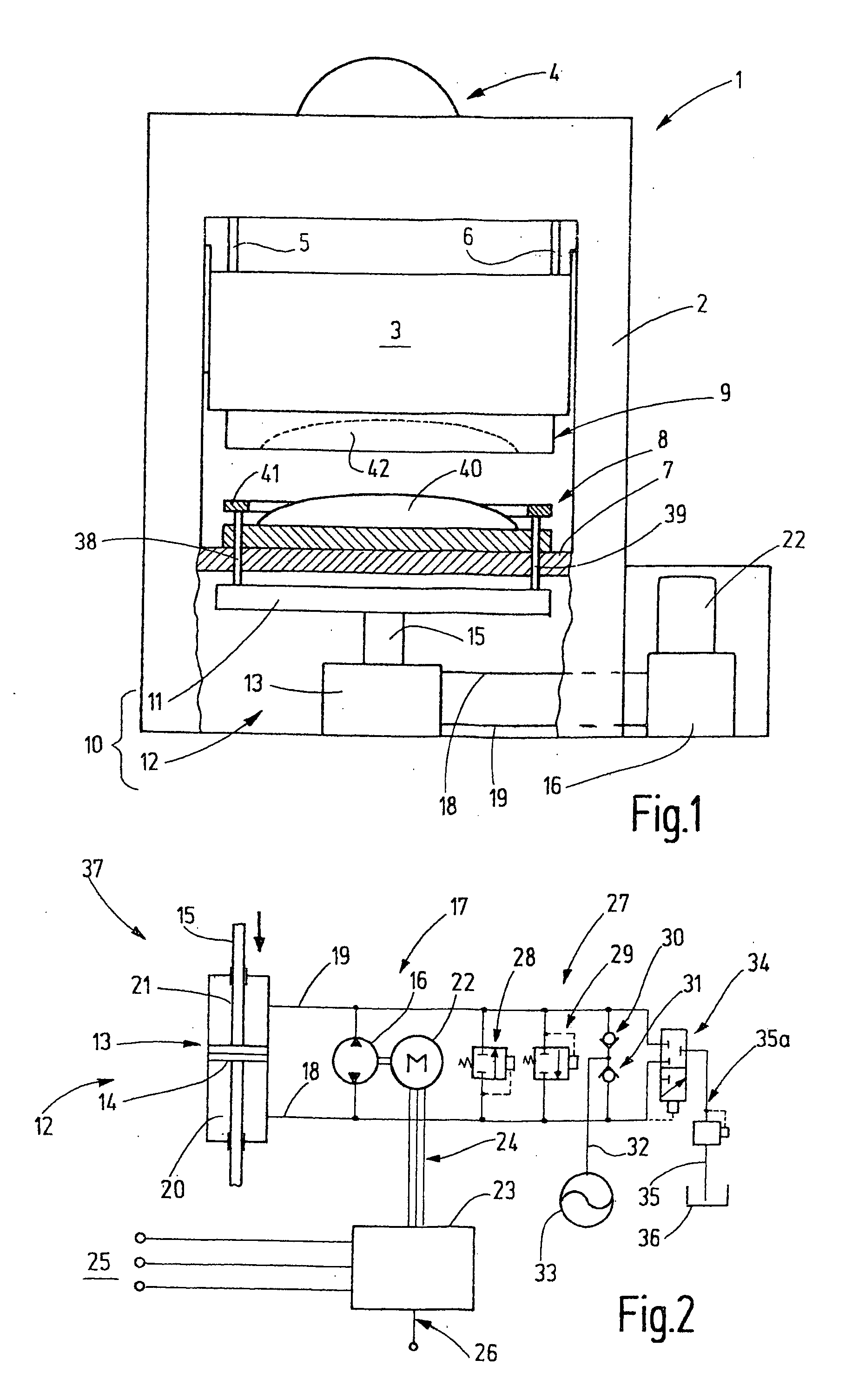
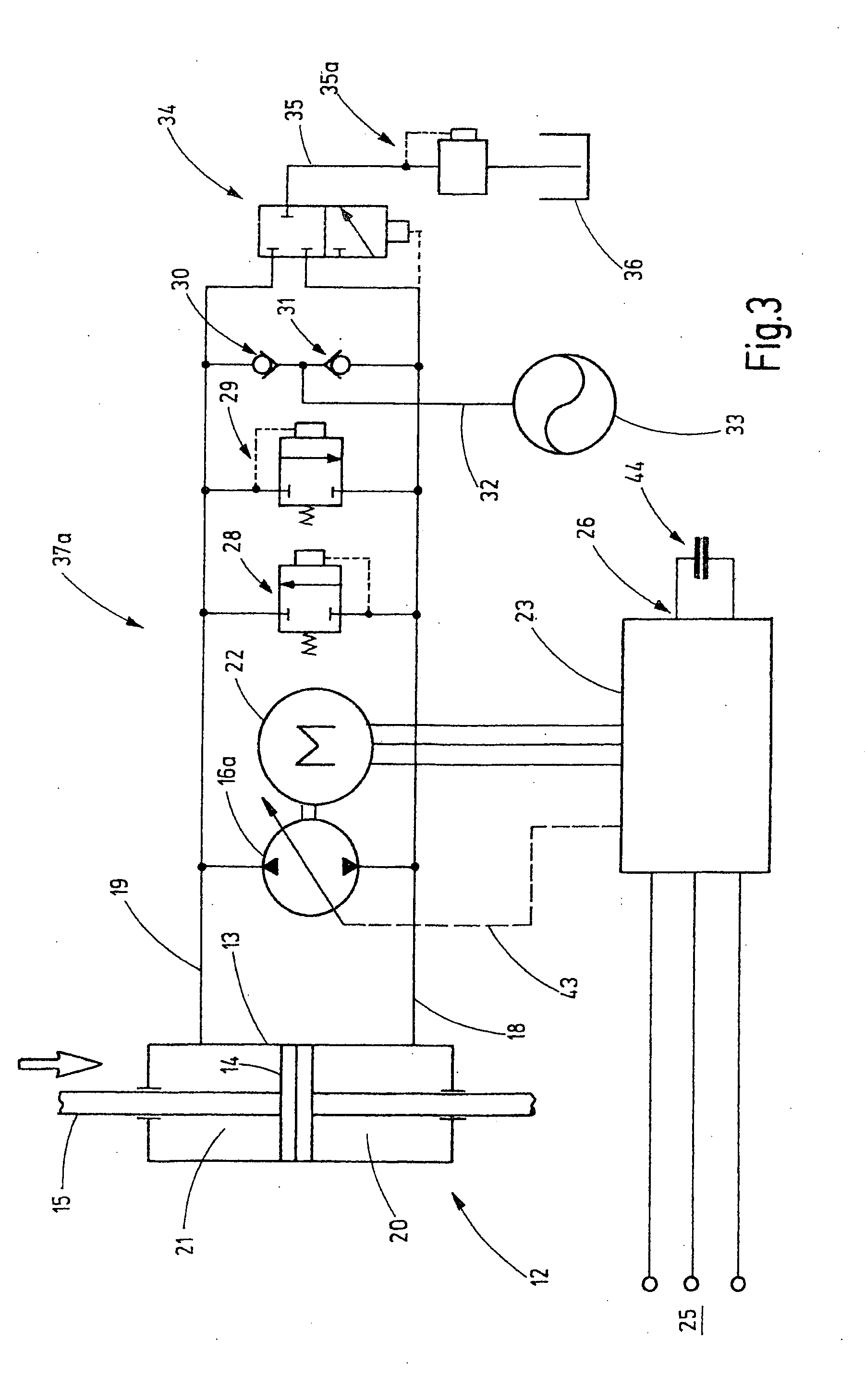
[0024]Below the press table 7, the drawing cushion 10 is arranged which includes a floating plate 11 and at least one hydraulic motor 12. The hydraulic motor is formed by at least one (or several) hydraulic cylinder 13, whose piston 14 is connected to the floating plate 11 by a piston rod 15. The hydraulic motor 12 is part of a hydraulic drive which includes a pump 16. In this hydraulic circuit 17 shown in FIG. 2, the pump 16 is...


PUM

PropertyMeasurementUnit
electric energyaaaaaaaaaa
forceaaaaaaaaaa
energyaaaaaaaaaa

Abstract

In an electrohydraulic drawing press drive, particularly an electrohydraulic drawing cushion drive including a hydraulic circuit with at least one motor which is operable as a drive motor or as a pump and at least one hydraulic pump which is operable as a pump or as a drive motor, an electric drive motor which is also operable as generator is connected to the hydraulic motor in order to drive the hydraulic motor or to be driven thereby and a control unit is provided for controlling at least one of the electric motor and the hydraulic pump.

Description

CROSS-REFERENCE TO RELATED APPLICATION[0001]This application claims the priority benefits of German Application No. 10 2006 058 630.1 filed Dec. 13, 2006.BACKGROUND OF THE INVENTION[0002]The invention relates to an electrohydraulic press or auxiliary drive arrangement, particularly an electrohydraulic drawing cushion drive with energy recuperation.[0003]Draw cushions are used in drawing presses to generate a force in a direction opposite the press plunger movement, for example, in order to engage, a metal sheet holder, the edges of a metal sheet subjected to the drawing operation in order to hold them in position during the drawing process. The metal sheet holding ring provided therefore has to withstand at least one drawing stroke. In connection with vehicle body metal parts such a drawing stroke may be very large, that is, it may be up to 300 mm or even more. Since, under such circumstances, the force required to hold the metal sheet in place, a correspondingly large amount of ene...

Claims


Application Information

Patent Timeline
Patent Type & Authority Applications(United States)
IPC IPC(8): B21D24/02F16D31/02
CPCB21D24/02B30B15/166F15B21/14F15B2211/20515F15B2211/20561F15B2211/88F15B2211/50527F15B2211/613F15B2211/625F15B2211/7053F15B2211/20569
Inventor MICKLISCH, MICHAEL
Owner SCHULER PRESSEN GMBH & CO KG
Why Eureka
Try Eureka