Liquid ejecting apparatus

a liquid ejecting and apparatus technology, applied in printing, other printing apparatus, etc., can solve the problems of maintenance work, risk of liquid leaking from the head flow path, and troublesome handling in this sta

Active Publication Date: 2017-05-04
SEIKO EPSON CORP
View PDF4 Cites 3 Cited by
  • Summary
  • Abstract
  • Description
  • Claims
  • Application Information

AI Technical Summary

Benefits of technology

[0007]An advantage of some aspects of the invention is that a liquid ejecting apparatus is provided whereby leakage of liquid from a head flow path can be prevented and maintenance can be performed in a short period of time.
[0009]According to this configuration, the attaching and removing of the attaching member that is attachable at the position adjacent to the head flow path can be associated with the opening and the closing of the head flow path. As such, the attaching member is removed from the position adjacent to the head flow path before the head flow path is removed from the liquid ejecting head and, therefore, the head flow path can be closed in advance by the opening / closing mechanism. Accordingly, when removing the head flow path in order to replace the liquid ejecting head or the like, leaking of the liquid can be prevented, maintenance can be performed in a short period of time, and serviceability can be improved.
[0011]According to this configuration, the head flow path can be closed from the outside by removing the attaching member that is attached outside the head flow path and, therefore, leaking of the liquid can be reliably prevented.
[0017]According to this configuration, the interfering portion disables the operation of the first fixing member and, therefore, unless the attaching member is removed in advance, the head flow path cannot be removed from the liquid ejecting head. As a result, situations can be avoided where the head flow path is removed from the liquid ejecting head while the head flow path is not closed, which would lead to leaking of the liquid.
[0019]According to this configuration, the attaching member is removed when the second fixing member operates and releases the fixing between the liquid ejecting head and the supporting member. As a result, the head flow path can be closed simultaneously with the releasing of the fixing between the liquid ejecting head and the supporting member.

Problems solved by technology

However, the head flow path is in a state filled with liquid and handling in this state is problematic.
Consequently, unless the head flow path is removed slowly, the seal will be imperfect, resulting in a risk of the liquid leaking from the head flow path at a time of replacing the liquid ejecting head.
Additionally, maintenance work needs to be performed in a short period of time in order to minimize downtime of the liquid ejecting apparatus and, if the liquid leaks, unnecessary cleaning time may be required.
According to this configuration, the interfering portion disables the operation of the first fixing member and, therefore, unless the attaching member is removed in advance, the head flow path cannot be removed from the liquid ejecting head.

Method used


Image

  • Liquid ejecting apparatus
  • Liquid ejecting apparatus
  • Liquid ejecting apparatus

Examples


first embodiment

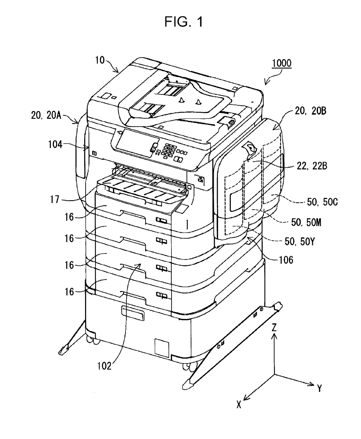
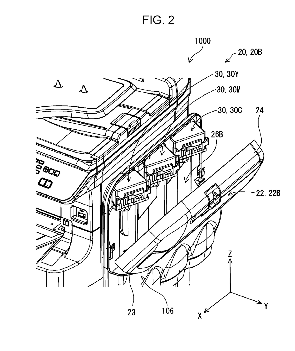
[0035]FIG. 1 is a perspective view illustrating an overall appearance of a liquid ejecting apparatus 1000 according to a first embodiment of the invention. FIG. 2 is a perspective view illustrating the liquid ejecting apparatus 1000 according to the first embodiment of the invention, in a state where a side portion is opened.

[0036]Note that, in FIGS. 1 and 2, an XYZ orthogonal coordinate system is set. In the liquid ejecting apparatus 1000, a front / rear direction is the X-axis direction, a direction orthogonal to the X-axis direction in the horizontal plane is the Y-axis direction (horizontal direction), and a direction (vertical direction) orthogonal to each of the X-axis direction and the Y-axis direction is the Z-axis direction.

[0037]As illustrated in FIG. 1, the liquid ejecting apparatus 1000 includes an apparatus body 10 and two liquid supplying devices 20. In a state of usage of the liquid ejecting apparatus 1000, the apparatus body 10 is set on a horizontal plane defined by t...

second embodiment

[0084]Next, a second embodiment of the invention will be described. In the following description, constituents that are identical or equivalent to those recited in the first embodiment are assigned the same reference signs and description thereof if simplified or omitted.

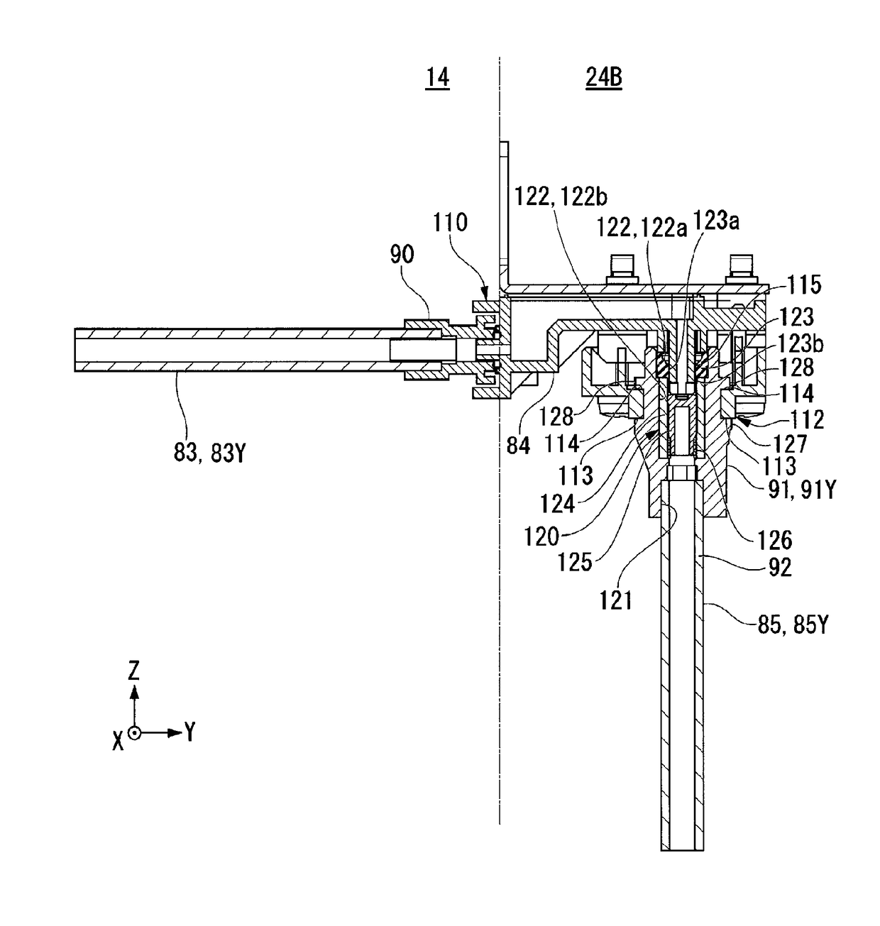
[0085]FIG. 11 is a side view illustrating an attached state of an attaching member 130A according to a second embodiment of the invention. FIG. 12 is a cross-sectional view illustrating an open state of the head flow path 81 according to the second embodiment of the invention. FIG. 13 is a cross-sectional view illustrating a closed state of the head flow path 81 according to the second embodiment of the invention.

[0086]As illustrated in FIG. 11, an attaching member 130A of the second embodiment is fixed together with the liquid ejecting head 60 to the supporting member 61 via the fixing member 62 (second fixing member). The attaching member 130A has a rough gate-like shape and, as illustrated in FIG. 11, when the at...


PUM


Abstract

A liquid ejecting apparatus including a liquid ejecting head that ejects liquid; a head flow path connected to the liquid ejecting head, that supplies the liquid; an attaching member that is attachable at a position adjacent to the head flow path; and an opening / closing mechanism that opens the head flow path when the attaching member is attached at the adjacent position and closes the head flow path when the attaching member is removed from the adjacent position.

Description

BACKGROUND[0001]1. Technical Field[0002]The present invention relates to a liquid ejecting apparatus.[0003]2. Related Art[0004]Ink jet printers have been known as an example of a liquid ejecting apparatus that perform printing on paper (recording media) by ejecting ink (liquid) from an ink jet head (liquid ejecting head). In such liquid ejecting apparatuses, in some cases a head flow path connected to a liquid ejecting head is removed in order to perform maintenance on the liquid ejecting head. However, the head flow path is in a state filled with liquid and handling in this state is problematic.[0005]JP-A-2001-18412 describes an ink jet recording apparatus including a joint portion for connecting a recording head. The joint portion includes a joint cylinder for connecting a supply tube, a joint cap formed from an ink-sealing member for preventing ink within the joint cylinder from leaking, and slender ink supply needle to be fixed and attached in a cylinder cap. According to the te...

Claims


Application Information

Patent Timeline
Patent Type & Authority Applications(United States)
IPC IPC(8): B41J2/175
CPCB41J2/17523B41J2/17596B41J2/175B41J2/17509B41J29/13
Inventor NAKAMURA, KOTAROMANO, TAKASHI
Owner SEIKO EPSON CORP
Why Eureka
Try Eureka