Brake Wear Analysis System

a technology of wear analysis and brakes, applied in the direction of brake systems, failure-safe aspects, braking components, etc., can solve the problems of more significant failure of the braking system b>200/b> through extended use, and provide false positive readings

Inactive Publication Date: 2017-05-04
CATERPILLAR INC
View PDF4 Cites 10 Cited by
  • Summary
  • Abstract
  • Description
  • Claims
  • Application Information

AI Technical Summary

Benefits of technology

[0008]In one aspect of the disclosure, a brake wear analysis system is disclosed for use on a work machine. The brake wear analysis system may have a brake charge system and at least one accumulator connected to the brake charge system. The at least one accumulator may be able to store a pressurized fluid received from the brake charge system. A brake control valve would then be able to receive the stored pressurized fluid from the at least one accumulator based on an input indicative of a braking action. Additionally, at least one pressure sensor may be fluidly coupled to the brake charge system to indicate an accumulator pressure of the pressurized fluid of the at least one accumulator. A controller would then be connected to the at least one pressur

Problems solved by technology

Over time, this wearable disc or pad disintegrates from the friction used to brake the work machine.
Additionally, this allows the maintenance technicians to address simple maintenance issues which, if not detected early, may lead to a more significant failure

Method used


Image

  • Brake Wear Analysis System
  • Brake Wear Analysis System
  • Brake Wear Analysis System

Examples


Embodiment Construction

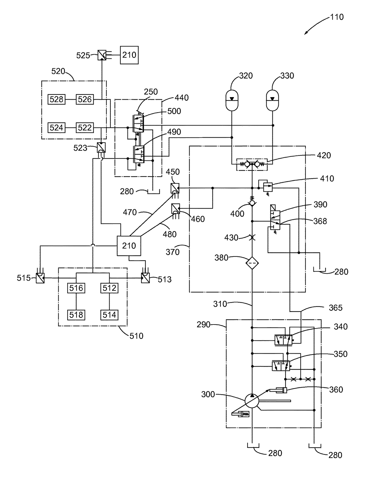
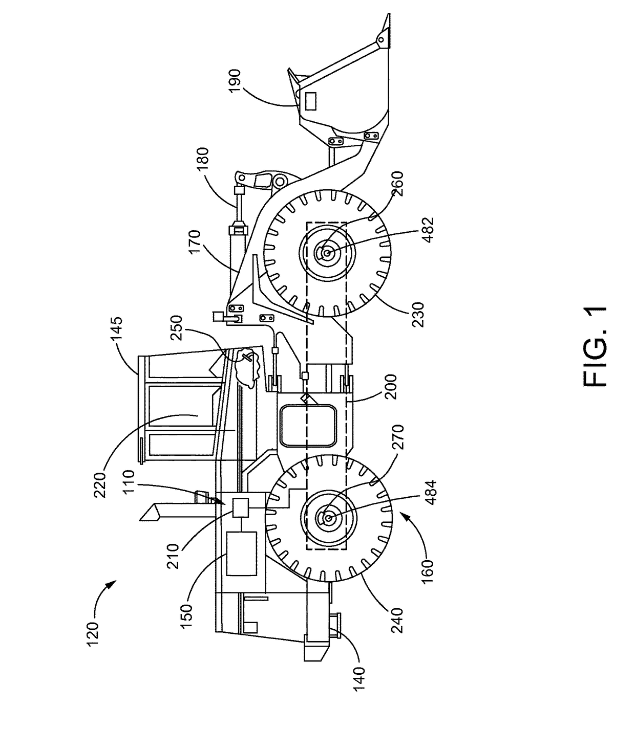
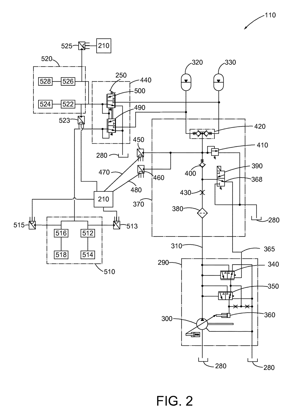
[0018]The present disclosure provides a brake wear analysis system 100 used in conjunction with a brake charge system 110 of a work machine 120. Examples of such work machines 120 include but are not limited to machines used for construction, earthmoving, mining, forestry, and other similar industries. Those skilled in the art will understand that the strategy in accordance with the present disclosure may be implemented in other types of work machines 120 as well. Moreover, references to various elements described herein, are made collectively or individually when there may be more than one element of the same type. However, such reference are rendered to merely aid the reader's understanding of the present disclosure and to be considered as exemplary. Accordingly, it may be noted that any such reference to elements in the singular is also to be construed to relate to the plural and vice versa without limiting the scope of the disclosure to the exact number or type of such elements ...


PUM


Abstract

A brake wear analysis system is presented for use within a work machine. The brake wear analysis system includes a brake charge system as well as at least one accumulator connected to the brake charge system. The at least one accumulator operable to flow a fluid from the accumulator to a brake control valve based on an executed braking action. A change of pressure within the at least one accumulator being received by a pressure sensor connected to the brake charge system and transmitted to a brake wear analysis module within the controller of the work machine. The brake wear analysis module being configured to compare the flow of fluid from the at least one accumulator with a predetermined condition resulting in a determination of whether or not a braking mechanism of the work machine is functioning in a worn condition.

Description

TECHNICAL FIELD[0001]The present disclosure generally relates to the braking system of a work machine, and more particularly relates to an analysis system to determine a wear condition of the brakes of such a braking system.BACKGROUND[0002]Earthmoving and work machines are used in a variety of industries including construction, mining, forestry, and other similar industries. Such work machines often employ hydraulic systems that provide functionality and control the various aspects of the machines. The hydraulic systems on the work machines may include braking systems to control driving speed, fan hydraulic drive systems to control machine cooling, and drive operation systems to control machine attachments such as tools, buckets, and loaders. Each hydraulic system of a work machine is generally an isolated system. These systems may have separate flow requirements, each with a separate fluid pump. In some other operational scenarios, the hydraulic systems may be combined, yet each se...

Claims


Application Information

Patent Timeline
IPC IPC(8): B60T17/22F16D66/02
CPCB60T17/221B60T2270/40B60T2270/88F16D66/02F16D2066/005
Inventor MATE, EDWARD W.DU, ZHANGONGSONO, SHINYA
Owner CATERPILLAR INC
Why Eureka
Try Eureka