Supercharge Your Innovation With Domain-Expert AI Agents!

Flapper valve adaptor for a roof vent and method of installing the same

a technology of adaptor and roof vent, which is applied in the field of roof vents, can solve the problems of low activation pressure, low safety, and loss of energy, and achieve the effects of low profile, low activation pressure, and convenient us

Active Publication Date: 2017-05-04
CANPLAS INDS
View PDF37 Cites 3 Cited by
  • Summary
  • Abstract
  • Description
  • Claims
  • Application Information

AI Technical Summary

Benefits of technology

The present invention is a versatile adaptor that can be used with different vent body designs. It includes a low profile design with a reliable flapper valve that can be easily mounted to a forced air duct. The design allows for control over the rotation of the flapper valve and requires minimal activation pressure for opening and closing. It is durable and can be easily retrofit to existing installations, and can be used with various roof vent styles and forms. Overall, the present invention provides an efficient and easy-to-use adaptor for mounting on the end of a forced air discharge duct.

Problems solved by technology

The removal of such moist air will limit the formation of mould or the like which can be a cleanliness and safety issue.
While this provides some protection for the discharge end of the duct it is generally not sufficient, in that there may be no provision of a flapper valve.
Without a flapper valve this can lead to drafts in the bathroom and a loss of energy.
The flapper doesn't allow the moist air to freeze.
While providing a flapper valve option for the specific roof vent design shown there are certain problems associated with this prior design.
The use of separate components leads to the risks of installer error and leaks.
Thus this prior adaptor combination is limited to being used with a roof vent the same as or substantially the same as what is shown.

Method used


Image

  • Flapper valve adaptor for a roof vent and method of installing the same
  • Flapper valve adaptor for a roof vent and method of installing the same
  • Flapper valve adaptor for a roof vent and method of installing the same

Examples


Embodiment Construction

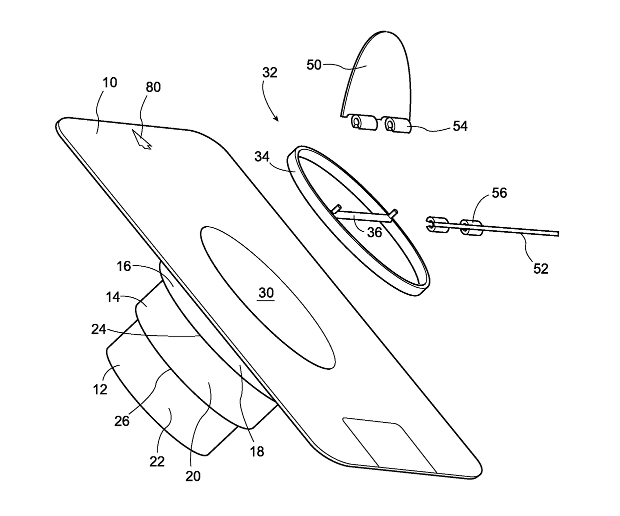
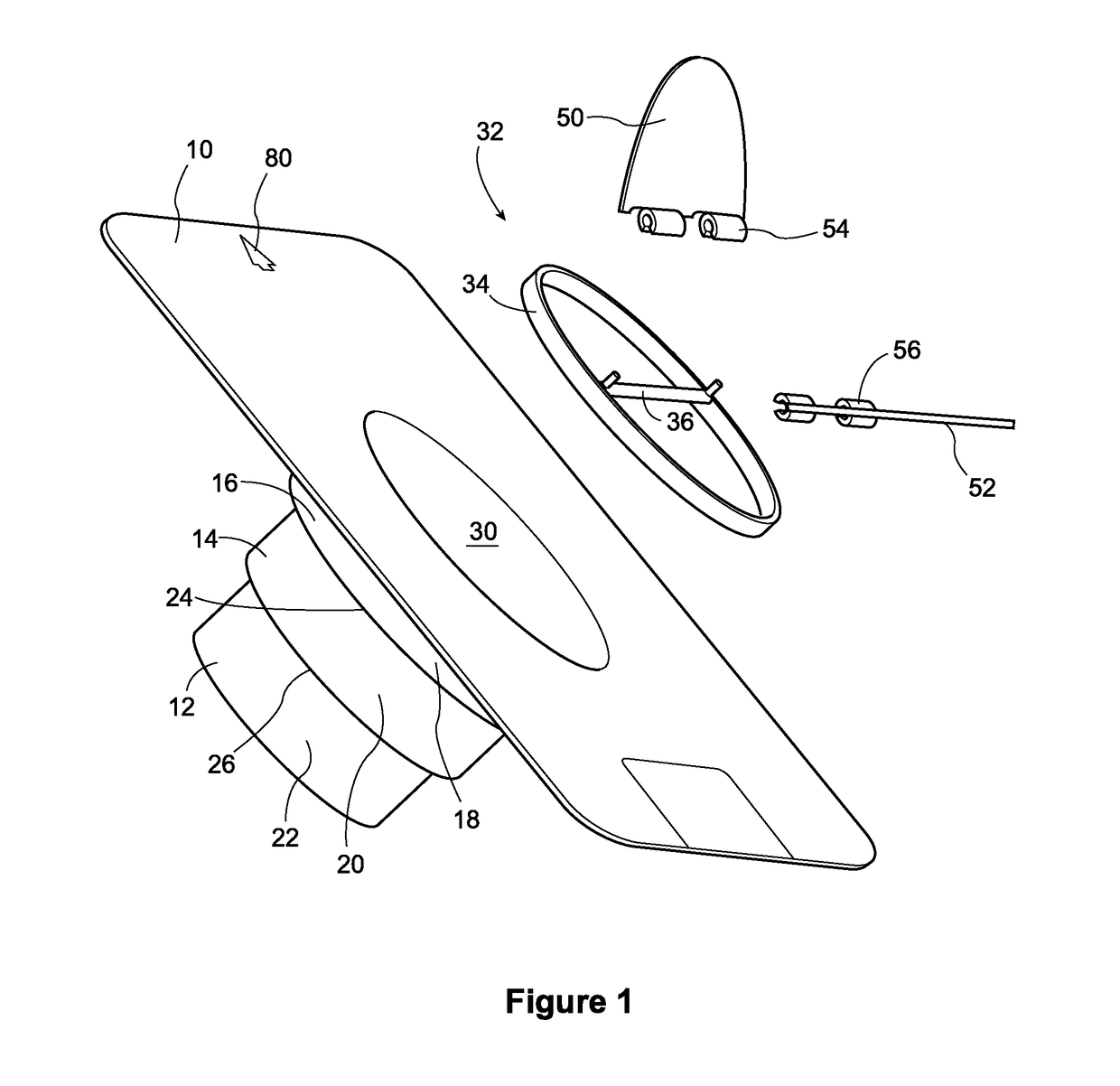
[0031]FIG. 1 shows an adaptor collar according to the present invention. As shown the adaptor collar has an attachment base 10 from which extend number of different sized collars 12, 14, and 16. Each collar section is comprised of a duct attachment portion 18, 20 and 22 separated by horizontal steps 24 and 26. The smallest diameter connector 12 is the furthest from the base 10 and each successive connector section 14, 16 is of a larger diameter. Three sizes are believed to cover the usual range of ducts that might be used in typical duct work in a building. It will be understood that the collar sections that are too small to match the air duct which attaches to the adaptor may be trimmed off before the air duct connection is made.

[0032]It will also be understood that the duct collar sections 12, 14, and 16 are integrally moulded to each other and the last or largest one 16 is integrally moulded to the base 10. In this way once the duct is attached to the appropriate sized collar 12,...


PUM


Abstract

An adaptor for a passive roof vent is presented having a base securable to a roof deck and an integrally moulded stepped collar extending from the base on one side for connecting to different air duct sizes which defines a discharge end for an air flow passageway. A central well is defined by the collar adjacent to and below the base and is open towards the other side of the base and has a hinge pin for at least one flapper valve retained in the well below the base. At least one flapper valve, hinged to the hinge pin, pivots about a closed position to which the flapper valve is biased by gravity and an open position in which the flapper valve is opened by air pressure from below within the air flow passageway. The flapper valve remains partially within the well when the flapper valve is open.

Description

FIELD OF THE INVENTION[0001]This invention relates generally the field of roof vents, and more particularly to the type of roof vents that may be used to provide ventilation from a building enclosure. Most particularly this invention relates to the type of roof vents that may require a flapper valve, such as is common with forced air venting from, for example, bathroom fans, range fans and the like.BACKGROUND OF THE INVENTION[0002]Exhaust fans are often provided to suck moist air from bathrooms, smoke and steam from kitchens, and for other reasons. They are particularly useful in removing moist air from bathrooms where for example showering may take place which can create a great deal of steam. The removal of such moist air will limit the formation of mould or the like which can be a cleanliness and safety issue. Usually such bathroom fans are activated by a separate switch and can be turned on or off at will. Alternatively they may be automatically operated when there is enough moi...

Claims


Application Information

Patent Timeline
IPC IPC(8): F24F7/02E04D13/17F16K1/18
CPCF24F7/025E04D13/17F16K1/18F16K24/04
Inventor MANTYLA, JAMES BRIANBALDWIN, SCOTT
Owner CANPLAS INDS
Features
  • R&D
  • Intellectual Property
  • Life Sciences
  • Materials
  • Tech Scout
  • Unparalleled Data Quality
  • Higher Quality Content
  • 60% Fewer Hallucinations
Learn More