Trigger group for semi-automatic firearms

Active Publication Date: 2017-05-04
FRANKLIN ARMORY HLDG INC
View PDF1 Cites 40 Cited by
  • Summary
  • Abstract
  • Description
  • Claims
  • Application Information

AI Technical Summary

Benefits of technology

[0009]There has thus been outlined, rather broadly, the more important features of the invention in order that the detailed descrip

Problems solved by technology

However, Hawbaker's trigger system suffers from multiple disadvantages.
This attribute greatly increases the likelihood of an accidental discharge occurring from manipulating the se

Method used


Image

  • Trigger group for semi-automatic firearms
  • Trigger group for semi-automatic firearms
  • Trigger group for semi-automatic firearms

Examples


Embodiment Construction

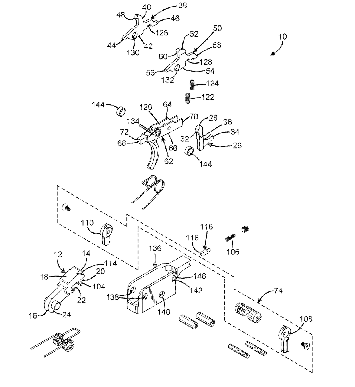
[0029]An embodiment of the trigger group for semi-automatic firearms of the present invention is shown and generally designated by the reference numeral 10.

[0030]FIG. 1 illustrates the improved trigger group for semi-automatic firearms 10 of the present invention. More particularly, the trigger group for semi-automatic firearms 10 has a hammer 12, backup disconnector 26, binary disconnector 38, semi-automatic disconnector 50, trigger 62, and safety selector assembly 74. When assembled, the hammer, backup disconnector, binary disconnector, semi-automatic disconnector, trigger, and safety selector are connected to a housing 136. Each side of the housing has a front aperture 138, a central aperture 140, and a rear aperture 142. A portion of the housing adjacent to the left rear aperture defines a cam surface 146. The apertures receive cross-pins (unlabeled) that are received within axles (unlabeled), which are cylinders with a thru-hole. The cross-pins hold the trigger group for semi-a...


PUM


Abstract

Trigger groups for semi-automatic firearms have a frame, a hammer connected to the frame and movable between a cocked position and a striking position, the hammer being biased toward the striking position, a trigger element connected to the frame and movable by a user between a forward position and a rearward position, a selector connected to the frame and movable between at least a first position and a second position, and a plurality of retention facilities each operable to selectively restrain the hammer in the cocked position, and when the selector is in the second position to enable discharge of the firearm in response to movement of the trigger to the forward position after movement to the rearward position and to enable an additional discharge of the firearm upon release of the trigger to the forward position.

Description

CROSS-REFERENCE TO RELATED APPLICATION[0001]This application claims the benefit of U.S. Provisional Patent Application No. 62 / 250,337 filed on Nov. 3, 2015, entitled “BINARY FIRING SYSTEM™ (aka BFS™),” which is hereby incorporated by reference in its entirety for all that is taught and disclosed therein.FIELD OF THE INVENTION[0002]The present invention relates to firearms, and more particularly to a trigger group for semi-automatic firearms.BACKGROUND OF THE INVENTION[0003]A trigger group includes all parts of the firearm that initiate the firing of the bullet. Parts include the trigger, which is usually a lever that is tripped by one or more fingers of the firing hand; the sear, which holds the hammer back until the trigger has been pulled; a disconnector, which keeps the hammer in place until the trigger is released and the sear takes over after a cycle of semi-automatic fire has occurred; and several springs throughout the group. The sear may be a separate part or can be a surfac...

Claims


Application Information

Patent Timeline
IPC IPC(8): F41A19/24F41A19/10F41A19/16F41A19/45
CPCF41A19/24F41A19/16F41A19/10F41A19/45F41A17/74F41A19/06F41A19/12F41A19/46
Inventor FELLOWS, RYAN PAULJACOBSON, JAY LEONARD
Owner FRANKLIN ARMORY HLDG INC
Why Eureka
Try Eureka