
Molds for custom dental implant abutments and impression posts

a technology for dental implants and impression posts, which is applied in the field of molds for custom dental implant abutments and impression posts, can solve the problems of not being able to recommend modification, limit the choice of shape, size and material of fabrication, and dentists faced a significant problem, so as to improve the final esthetic and biological outcome, the effect of high polishing

Active Publication Date: 2017-05-11
VP INNOVATO HLDG LTD
View PDF22 Cites 17 Cited by
  • Summary
  • Abstract
  • Description
  • Claims
  • Application Information

AI Technical Summary

Benefits of technology

The invention provides a mold made of metal or ceramic that is more durable and can be used more frequently compared to molds made only of elastomeric materials. The mold can be prepped and used to create temporary prosthesis that can be cemented onto abutments. This process is simple and helps prevent damage to the abutments, which improves the long-term stability of the implant.

Problems solved by technology

Thus, before the invention described herein, dentists faced a significant problem arising from the limitations in choice of shape, size and material of fabrication of the healing abutments and impression posts that are provided by the different implant companies.
The mismatch between the parts supplied by the different implant companies forces the dentists to change their utilized protocols of treatment between different clinical cases, depending on the company that supplied the utilized implant.
The healing abutments available on the market with their relatively narrow cylindrical shape generate a narrow gingival emergence profile and this creates difficulties at the stage of the final implant prosthesis installment onto the implant, due to the difference in shape and dimensions between the gingival emergence profile and the emergence profile of the final prosthesis.
The healing abutments available from most of the implant supply companies are made out of titanium and modifications to them are not recommended, even when modification is necessary.
Thus, the use of large size healing abutments in many clinical cases is impossible because their body will interfere with the adjacent teeth making their installation onto the implant without any modifications of their size and shape difficult to impossible.
The disadvantage of these healing abutments is that they are not customizable and thus they fail to generate a three dimensionally ideal shape gingival emergence profile in all clinical cases.
This does not allow the dentist to take full advantage of the tools that digital dentistry through CAD-Cam machinery potentially provides to the dentist.
Another important clinical problem is the accurate recording and transfer of the gingival emergence profile at the impression stage, from the mouth to the working cast, where the lab technician will fabricate the final implant prosthesis.
The impression posts available from the different implant companies have a narrow emergence profile that corresponds to the narrow emergence profile of the healing abutments they provide and do not have properties that allow their ready customization.
A dentist that has created a custom emergence profile through the use of a temporary prosthesis finds a difficult situation as to the way that they can record and transfer accurately the created custom gingival emergence profile from the mouth to the working cast, due to the difference in shape and dimensions of the latter as compared to the shape and the dimensions of the impression posts available to the dentist from the implant supply companies.
Angulated impression posts are not available in the market.
Thus, in clinical cases where the implant is located in the jaw with angulations different than the ones of the adjacent teeth, the dentist might not be able to install onto the implant a straight impression post as its body may interfere with the crowns of the adjacent teeth or the impression posts of the adjacent implants.
Moreover, at the stage of impression removal from the mouth the different angulations of the aforementioned elements might lead to the development of areas of deformation of the impression material around the impression post, a fact that negatively affects the precision of the impression.
The impression posts available today also do not have the design and properties that allow their ready modification to temporary abutments that can be used to support a temporary prosthesis.
In addition, a patient's soft tissue will not adapt as well to the irregular surfaces as it would to a regular surface.
The use of the additional biomaterial by U.S. Pat. No. 8,628,327B1 that is added to the well to make the abutment, and which expands in close relationship to its prosthetic platform, also detracts from the usefulness of this patent's method because it does not generate and establish a better zone of connective tissue attachment and adhesion and provide for the presence of a micro-gap between the different materials in this sensitive biologically area as does a regular surface and a material such as polished titanium.
In addition, if the wells of this patent were used to try to make an impression post, the impression post will not match the abutment because the patent teaches the use of the additional biomaterial to the abutment and thus the impression post made from the well will be different and the impression post cannot act as an exact replica that records and transfers the information into a working cast.
Thus, the patent does not teach that these parts can be interchangeably snapped onto the abutment core that is coupled to the implant, a feature that avoids the repetitive coupling and uncoupling that can induce harmful hard and soft tissue recession.
U.S. Pat. No. 8,628,327B1 also does not teach a mold with wells that make abutments and impression posts that can be oriented in different angulations towards the vertical plane by angulation of the sockets comprising prosthetic connections of the abutments and impression posts.

Method used


Image

  • Molds for custom dental implant abutments and impression posts
  • Molds for custom dental implant abutments and impression posts
  • Molds for custom dental implant abutments and impression posts

Examples


example 1

[0121]In a first example the edentulous space that has been generated from a missing tooth has received an implant that, due to bone width missing from the facial aspect of the alveolar ridge, has been placed by the surgeon with an angulation of twenty degrees towards the longitudinal axis of the final prosthesis that the implant will receive (FIG. 14). After the implant placement the surgeon couples with the implant a custom abutment with twenty degrees angulations (14.a) with a short retention screw (9.a). The custom abutment utilized has dimensions that correspond to the available prosthetic space. Specifically the custom abutment is located in the edentulous space in a way that its outer borders are within the line borders of the future prosthesis (20.z) without expanding out of this borders at any point and its custom body has an angulation that is parallel to the one of the longitudinal axis of the final prosthesis (FIGS. 14, 20). Following this, the surgeon sutures the gingiv...

example 2

[0122]In a second example (FIG. 18) a custom abutment (18.b) is coupled with an implant in the mouth (18.g) and the prosthetic rehabilitation of the implant with a temporary prosthesis (18.d) is desired, in order for a transitional loading of the implant to be achieved, before the implant receives its final prosthesis. At this stage the supra-gingival portion of the custom abutment (18.b) is prepped by abrasion from the dentist (18.a), following the same principles as per natural teeth preparation. Thus, the custom modified by abrading abutment now has a shape similar to that of a prepped tooth with supra-gingival prosthetic borders (18.e), while the emergence profile (14.b) of the modified abutment (18.b) remains intact since any abrading of the abutment takes place only supra-gingivally. Following this, the dentist takes an abutment level impression of the modified abutment (18.e) with the same principles as per natural abutment teeth impression. The impression is then sent to the...

example 3

[0123]In a third example (FIG. 21) in an edentulous jaw two implants have been placed on the right side, which present fifteen degree angulations towards the longitudinal axis of the final prosthesis, while at the left side two implants have been placed which present twenty-five degree angulations towards the longitudinal axis of the final prosthesis. Two custom abutments of fifteen degrees angulations (21.b, 21.bb) are coupled with the two implants of the right side and two custom abutments of twenty-five degree angulations (21.a, 21.aa) are coupled with the two implants of the left side. After the osseointegration period is passed the angulated custom abutments are uncoupled from the implants and four angulated custom impression posts, with corresponding to the abutments angulations and dimensions, replace them (21.d, 21.dd, 21.g, 21.gg). Following this, the dentist takes an implant level impression following the same steps as they have been previously described in the first examp...


PUM


Abstract

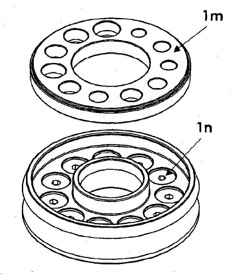
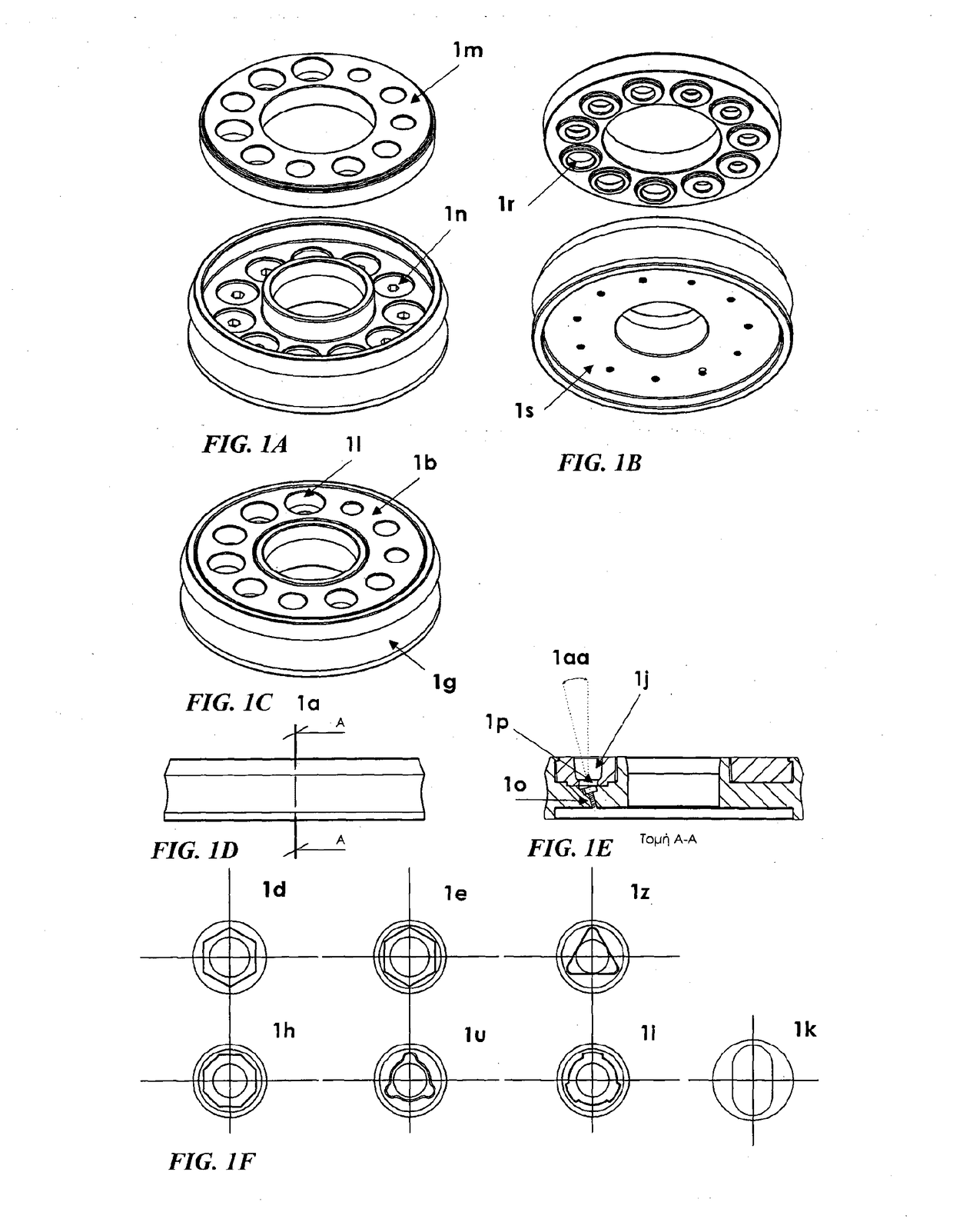
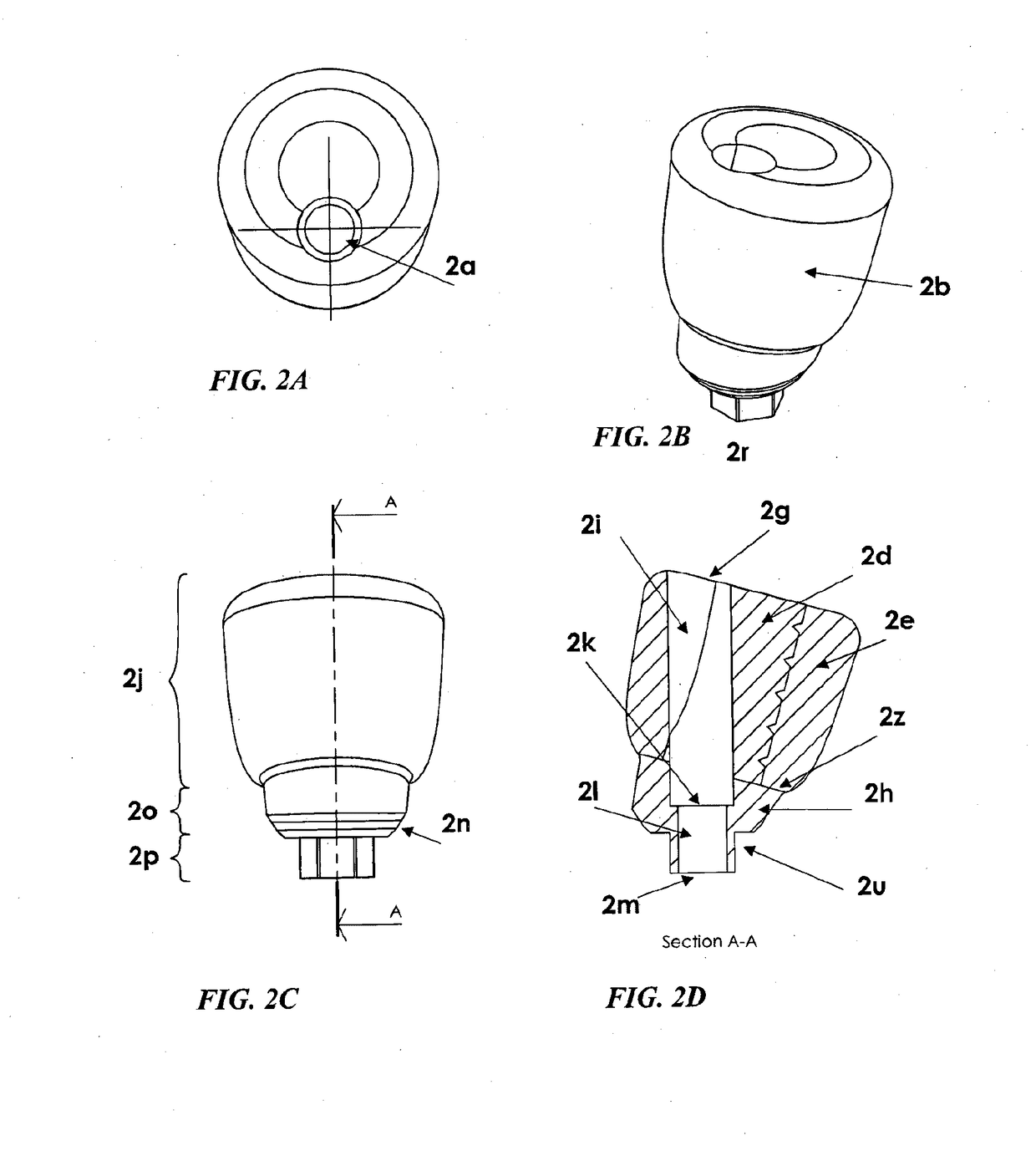
Molds for fabrication of custom and potentially modifiable abutments and impression posts for dental implants with various degrees of angulations (including zero degrees) and various dimensions are provided, with a generally oval shape that expands laterally upwards, a symmetrical or asymmetrical cross-section, and regular surfaces, that are fabricated as one piece, or as two coupling pieces snapping onto each other. Custom abutments achieve the development of a custom gingival emergence profile, three dimensionally, which is potentially modifiable according to the needs of each particular clinical case. Custom impression posts that correspond in dimensions and angulations to the abutments allow the accurate recording and transfer of the developed gingival emergence profile from the mouth onto the working cast, where the final implant prosthesis is fabricated. Custom abutments and impression posts have properties and design that allows their preparation and usage as temporary abutments for the cementation and support of temporary prostheses.

Description

[0001]This application claims the benefit and is a continuation-in-part of Greek Patent Application Serial Nos. 20140100327 (filed Jun. 13, 2014), 20140100642 (filed Dec. 16, 2014), 20150100090 (filed Mar. 4, 2015), and 20150100111 (filed Mar. 12, 2015), which are each incorporated by reference herein in their entirety.TECHNICAL FIELD[0002]This invention is directed to molds and methods of using molds for the fabrication of custom, intra-orally and extra-orally modifiable, abutments and impression posts that can be used in the surgical and prosthetic stage of dental implant treatment and the use of such abutments and impression posts in dental implant related procedures.BACKGROUND[0003]The replacement of missing and hopeless teeth with dental implants is a very common practice. Once an implant is surgically placed, it is usually allowed to heal for a time frame of a few weeks in order for the process of its osseointegration with the jaw to be completed, before it can receive its fin...

Claims


Application Information

Patent Timeline
IPC IPC(8): A61C13/20A61C9/00A61C13/15A61C8/00A61C13/107
CPCA61C13/206A61C8/0001A61C8/0056A61C8/0068A61C8/008A61C19/003A61C8/009A61C9/0006A61C9/0053A61C13/0001A61C8/005A61C8/0053A61C8/0063A61C8/0089A61C9/00A61C13/0003A61C13/0022A61C19/04A61C1/084A61C8/0012A61C13/0021
Inventor VERGOULLIS, IOANNISPAPADOPOULOS, GEORGIOS
Owner VP INNOVATO HLDG LTD
Learn More