
Liquid droplet jetting apparatus

a technology of liquid droplets and jetting apparatuses, which is applied in printing and other directions, can solve the problems of lowering image quality and image quality, and achieve the effects of reducing the amount of positional shift of target positions, and preventing any lowering of image quality

Active Publication Date: 2017-05-11
BROTHER KOGYO KK
View PDF3 Cites 1 Cited by
  • Summary
  • Abstract
  • Description
  • Claims
  • Application Information

AI Technical Summary

Benefits of technology

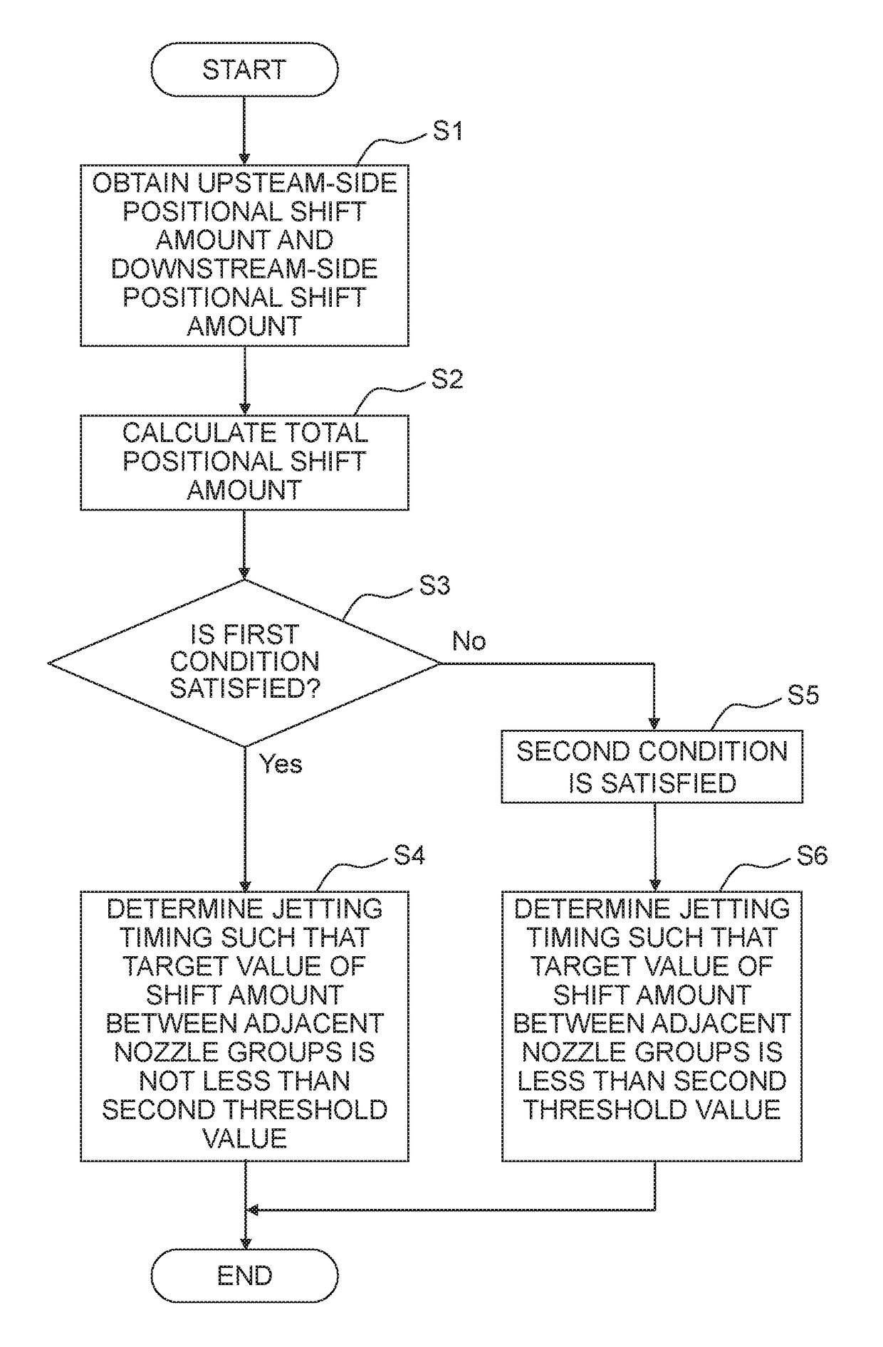
The present invention provides a liquid droplet jetting apparatus that can reduce image quality degradation by controlling the positional shift of the target positions of liquid droplets during printing. The controller determines the jetting timing so that the target value of the shift amount between the adjacent nozzle groups is not less than a predetermined threshold value, which allows for a small positional shift between the nozzle groups. This results in a more stable printing process and improved image quality.

Problems solved by technology

Therefore, in a case that this distance is varied or changed in a sub scanning direction of the recording medium, any shift in the landing position of the ink occurs among nozzles aligned in the sub scanning direction and between continuous pass printings, which in turn lowers the image quality.
Due to such a boundary, in a case that the jetting timing is corrected for each of the nozzle groups within a pass and that an image formed by a pass printing as a target (target pass printing) and another image adjacent to the image are not connected (continued) in the sub scanning direction, any boundary is unnecessarily formed between the nozzle groups within the pass, resulting in a lowered image quality.

Method used


Image

  • Liquid droplet jetting apparatus
  • Liquid droplet jetting apparatus
  • Liquid droplet jetting apparatus

Examples


first embodiment

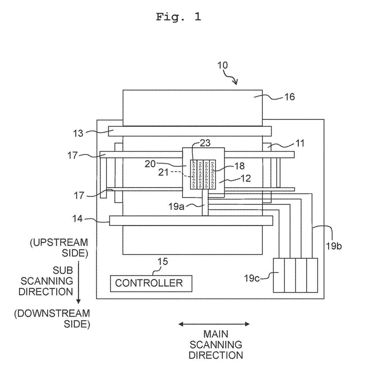
[0055]At first, the configuration of a liquid droplet jetting apparatus 10 will be explained with reference to FIG. 1. The liquid droplet jetting apparatus 10 is provided with a jetting head 20, a carriage 12, conveying sections 13 and 14, and a controller 15. The liquid droplet jetting apparatus 10 may be further provided with a paper supplying section (not depicted in the drawings) and a platen 11.

[0056]The paper feeding section is a mechanism which supplies a recording medium 16 inside a paper feed tray (not depicted in the drawings) to a conveying path. The platen 11 is a stand on which the supplied recording medium 16 is placed. The recording medium 16 is a paper, etc., on which an image. etc. is formed by liquid droplets jetted from nozzles 21 of the jetting head 20.

[0057]The carriage 12 is a member which holds the jetting head 20 and causes the jetting head 20 to reciprocate in a main scanning direction. For example, the carriage 12 is supported by two guide rails 17 extendin...

second embodiment

[0107]In a liquid droplet jetting apparatus 10 according to a second embodiment, the controller 15 determines that the second condition is satisfied in a case that at least one of a first printing data, a second printing data, a third printing data and a fourth printing data is a printing data which does not cause the liquid droplets to be jetted over an entire area in the main scanning direction (namely, a print data in which an amount of the liquid droplets to be jetted over the entire area in the main scanning direction is 0 (zero)).

[0108]The first printing data is a printing data which is included in a printing data for the target pass printing and which relates to downstream-most nozzles (downstream-end nozzles) 21 arranged on the most downstream side in the sub scanning direction. The second printing data is a printing data which is included in a printing data for the preceding pass printing and which relates to upstream-most nozzles (upstream-end nozzles) 21 arranged on the m...

third embodiment

[0114]In a liquid droplet jetting apparatus 10 according to a third embodiment, the controller 15 determines that the first condition is satisfied in a case that the first printing data and the second printing data both include a printing data for forming dots which are aligned in the sub scanning direction, and that the third printing data and the fourth printing data both include a printing data for forming dots which are aligned in the sub scanning direction.

[0115]Specifically, the controller 15 analyzes printing data located at a same location in the main scanning direction, regarding the first printing data and the second printing data. At a position S1 in the main scanning direction as depicted in FIG. 10B, each of the first printing data relating to the downstream-end nozzle 21 in the target pass printing and the second printing data relating to the upstream-end nozzle 21 in the preceding pass printing is a printing data which does not cause the liquid droplet to be jetted. A...


PUM


Abstract

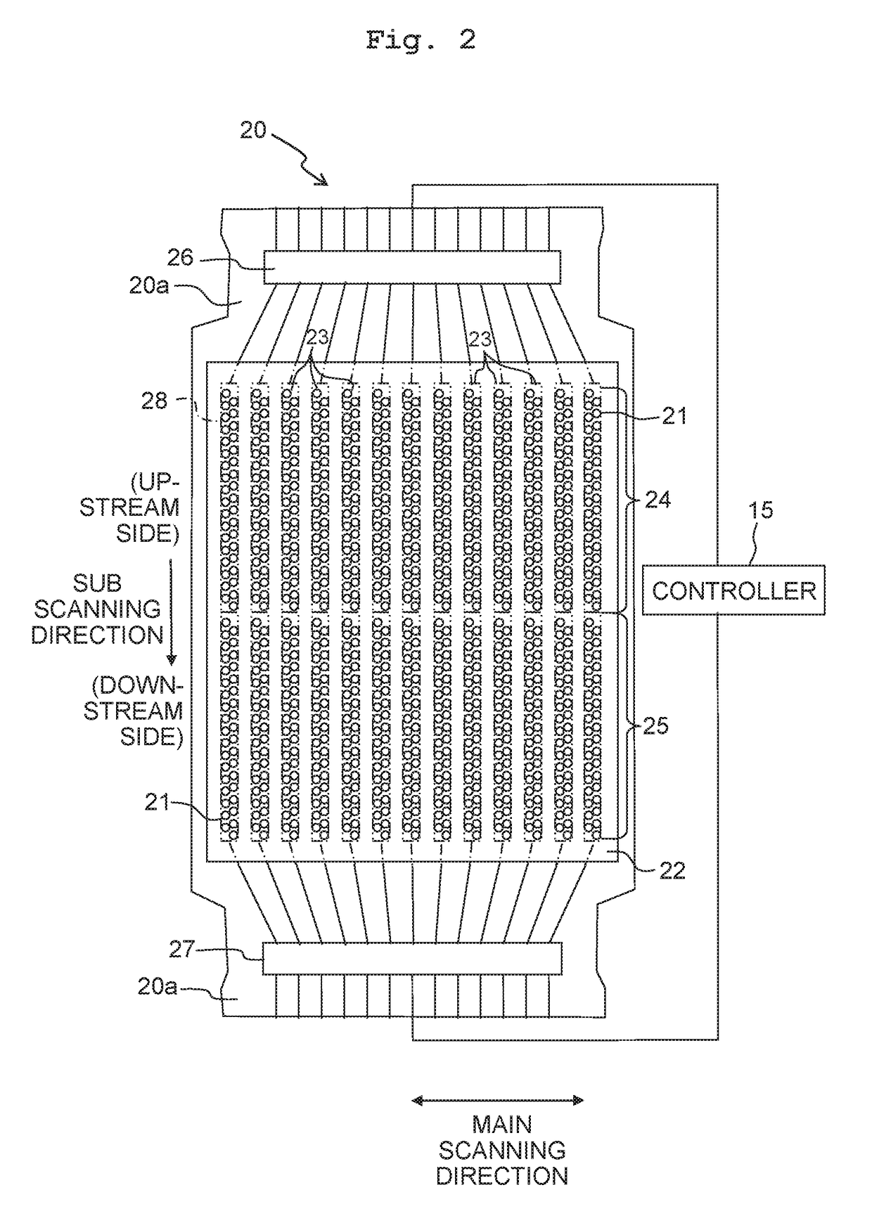
A liquid droplet jetting apparatus includes: a carriage configured to scan in a main scanning direction; a jetting head installed in the carriage, having nozzles arranged in a sub scanning direction intersecting with the main scanning direction, and configured to jet liquid droplets from the nozzles; a conveyer configured to convey the recording medium in the sub scanning direction; and a controller configured to control the carriage, the jetting head and the conveyer. The nozzles form nozzle groups including two nozzle groups adjacent in the sub scanning direction; and the controller is configured to execute a predetermined printing mode in which a pass printing and conveyance of the recording medium in the sub scanning direction are alternately performed. The pass printing causes the carriage to move one time in the main scanning direction while jetting the liquid droplets from the nozzles.

Description

CROSS REFERENCE TO RELATED APPLICATION[0001]The present application claims priority from Japanese Patent Application No. 2015-219632 filed on Nov. 9, 2015 the disclosure of which is incorporated herein by reference in its entirety.BACKGROUND[0002]The present invention relates to a liquid droplet jetting apparatus, particularly to a liquid droplet jetting apparatus provided with a jetting head and configured to perform recording on a recording medium by jetting liquid droplets from nozzles onto the recording medium.DESCRIPTION OF THE RELATED ART[0003]In an ink-jet printer as an example of the liquid droplet jetting apparatus, a landing position of ink jetted from a nozzle depends on the distance between the nozzle and a recording medium. Therefore, in a case that this distance is varied or changed in a sub scanning direction of the recording medium, any shift in the landing position of the ink occurs among nozzles aligned in the sub scanning direction and between continuous pass prin...

Claims


Application Information

Patent Timeline
Patent Type & Authority Applications(United States)
IPC IPC(8): B41J2/045
CPCB41J2/04586B41J2/04573B41J2/2132B41J2/2135
Inventor ARAKANE, SATORU
Owner BROTHER KOGYO KK
Learn More