
Optical scanning apparatus

Pending Publication Date: 2021-09-30
CANON KK
View PDF0 Cites 0 Cited by
  • Summary
  • Abstract
  • Description
  • Claims
  • Application Information

AI Technical Summary

Benefits of technology

The present invention relates to an optical scanning apparatus that can prevent the laser beam from shifting due to vibrations caused by the mirror. The invention achieves this by ensuring that the mirror is constantly in contact with a positioning portion, which reduces the shift amount of the laser beam.

Problems solved by technology

However, in a case where the optical box is a resin molded product, it is conceivable that the accuracy of the seating surface deteriorates due to a variation at the time of molding.
The deterioration in accuracy of the seating surface may make the orientation of the mirror unstable.

Method used


Image

  • Optical scanning apparatus
  • Optical scanning apparatus
  • Optical scanning apparatus

Examples


Embodiment Construction

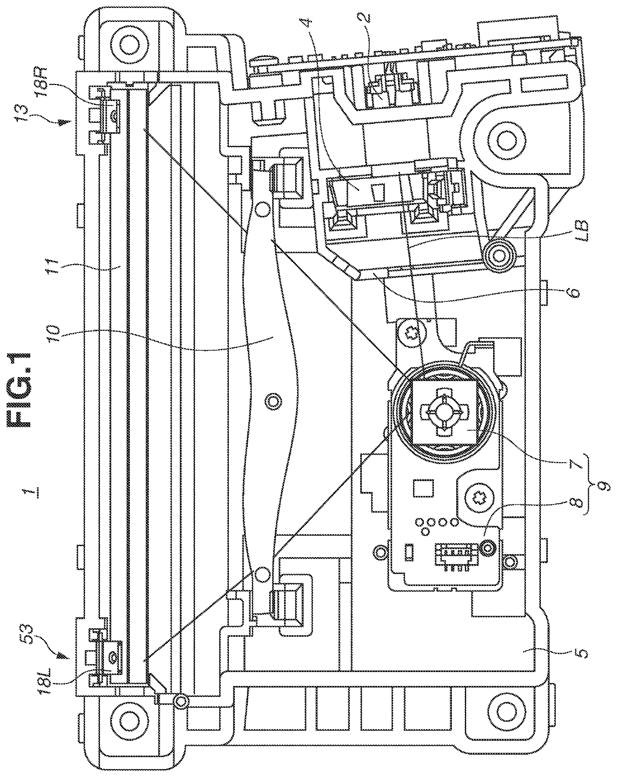
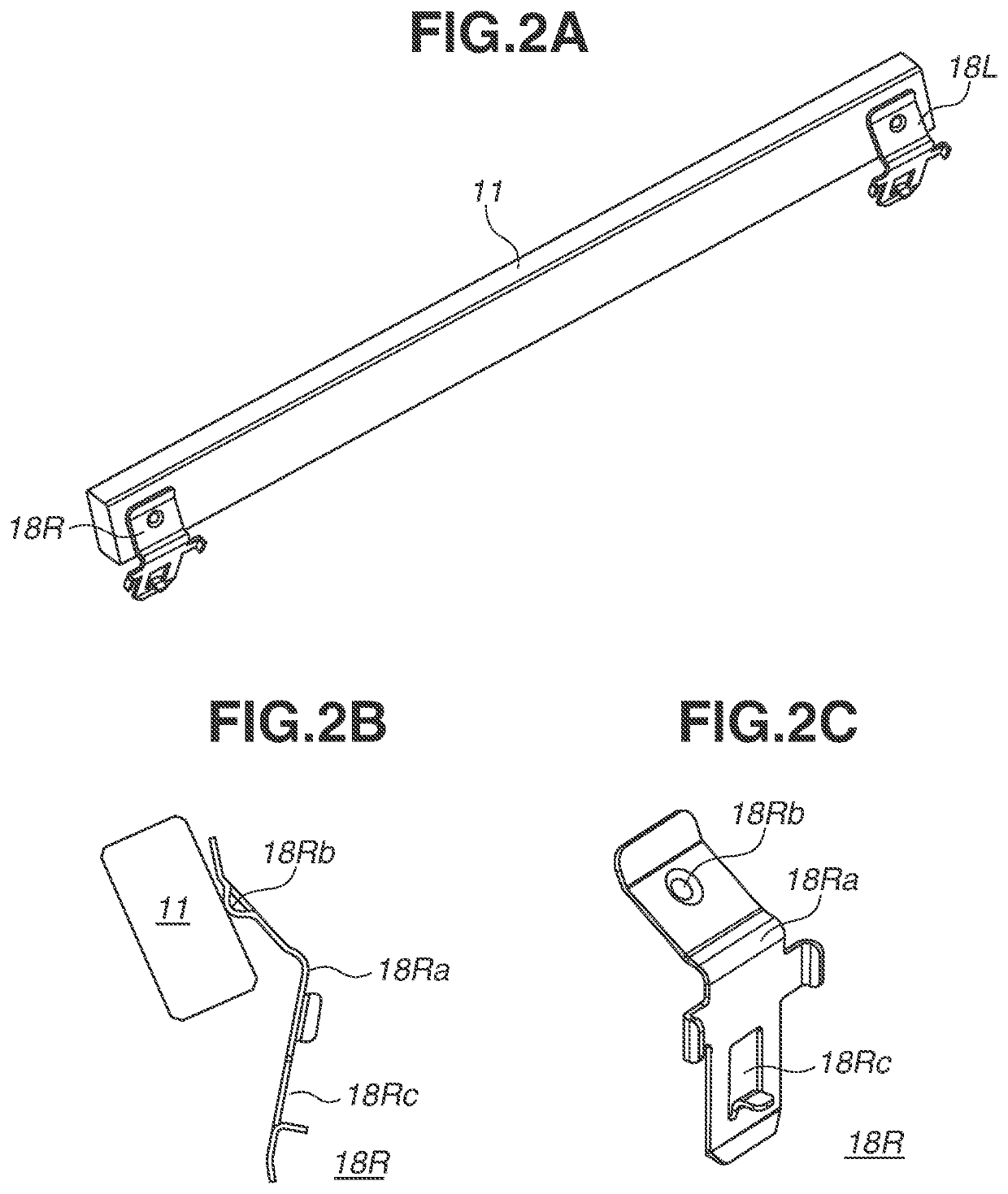
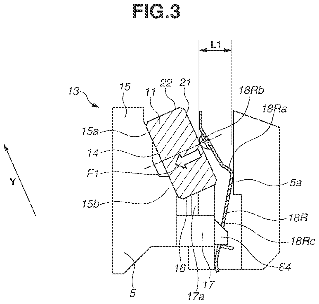
[0026]FIG. 1 is a plan view illustrating an optical scanning apparatus 1 according to an exemplary embodiment. A laser beam LB emitted from a light source unit (light source) 2 is collected by an anamorphic lens 4, and a beam diameter of the laser beam LB is restricted to a predetermined beam diameter by an optical diaphragm 6 formed in an optical box 5. Then, the laser beam LB is incident on a rotational polygon mirror 7. The rotational polygon mirror 7 is driven by a motor mounted on a driving circuit substrate 8 to deflect the laser beam LB incident thereon. The rotational polygon mirror 7 and the driving circuit substrate 8 constitute a deflector 9. The deflected laser beam LB, after passing through a fθ lens 10, is reflected on a long-length mirror 11, and scans a photosensitive member (not illustrated) mounted in an electrophotographic printer. As a result, an electrostatic latent image is formed on the photosensitive member. The mirror 11 is fixed to the optical box 5, which ...


PUM


Abstract

In an optical scanning apparatus, a first positioning portion has two seating surfaces that hold a mirror and a second positioning portion has only one seating surface that holds the mirror. A force of pressure of a first urging member is greater than a force of pressure of a second urging member, thereby preventing a vibration of the mirror.

Description

BACKGROUNDField of the Disclosure[0001]The present disclosure relates to an optical scanning apparatus used for an image forming apparatus using an electrophotographic method, such as a laser printer and a digital copying machine.Description of the Related Art[0002]In many cases, an optical scanning apparatus that scans a photosensitive member mounted in an electrophotographic image forming apparatus with a laser beam in accordance with image information is equipped with a mirror to deflect an optical path of the laser beam.[0003]If an orientation of the mirror is displaced from a desired orientation, an irradiation position of the laser beam to the photosensitive member is shifted. Thus, in an optical scanning apparatus discussed in Japanese Patent Application Laid-Open No. 2002-182144, a structure of holding a mirror is proposed to make the orientation of the mirror in the desired orientation.[0004]The mirror is typically positioned on a seating surface of an optical box by being ...

Claims


Application Information

Patent Timeline
IPC IPC(8): G02B26/10G02B26/08G03G15/043
CPCG02B26/105G03G15/043G02B26/0816G03G15/0409G02B26/125G02B7/182
Inventor MUROTANI, TAKU
Owner CANON KK
Learn More