Pipeline-waste-gas reduction method

a technology of waste gas and pipeline, applied in the direction of fluid pressure control, process and machine control, instruments, etc., can solve the problems of pollution source, high cost of replacement, high cost of procurement and installation, etc., and achieve the effect of increasing the control pressure returned, and reducing the amount of gas wasted

Active Publication Date: 2017-05-11
DEVILLE CHAD +1
View PDF0 Cites 1 Cited by
  • Summary
  • Abstract
  • Description
  • Claims
  • Application Information

AI Technical Summary

Benefits of technology

[0014]The present invention provides a pipeline-waste-gas reduction method to reduce the amount of gas wasted by existing high-pressure pipelines having existing pipeline controllers and existing actuator-based control valves, by reducing the pressure of gas sent to existing pipeline controllers by a determined factor, consequently reducing the amount of gas wasted by the controllers, and then increasing control pressure returned by the controllers by the same factor, ensuring that the proper control pressure is sent to the existing actuator-based control valves.
[0015]The present invention solves an existing problem of too much gas being vented to the atmosphere and wasted by existing pipeline controllers, without requiring replacement or extensive modification of existing pipeline equipment.

Problems solved by technology

This venting is a waste of gas and is a source of pollution, because the gas is mostly methane.
The existing gas-venting pipeline controllers and actuator-based control valves are already in place, are reliable, were expensive to procure and install, and would be expensive to replace.
The volumetric weight of the bellow increases and becomes greater than the weight of the liquid, which results in lowering of the bellows into the liquid.

Method used


Image

  • Pipeline-waste-gas reduction method
  • Pipeline-waste-gas reduction method
  • Pipeline-waste-gas reduction method

Examples


Embodiment Construction

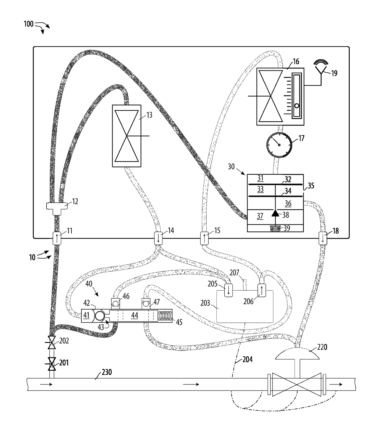
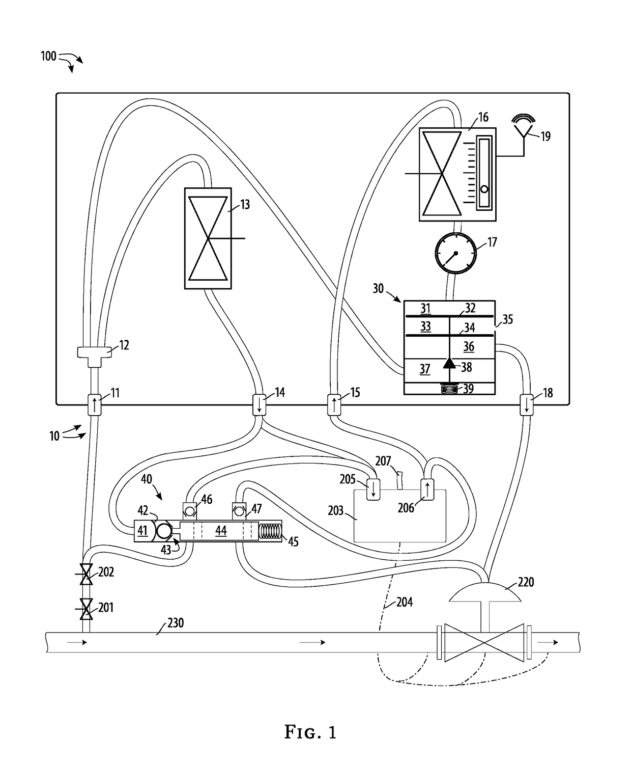
[0025]Referring to FIG. 1 and all figures generally, the pipeline-waste-gas reduction method 100 and the pipeline-waste-gas reducer apparatus 10 are shown schematically.

[0026]There are existing high-pressure pipelines 230 having control valves moved by existing actuators 220 under the control of existing controllers 203 having existing sensors and relays 204 to monitor and control the operation of the pipeline. Gas from the pipeline itself, at reduced pressure, is used as a motive force to operate the actuator 220 to close or partially close the pipeline control valve.

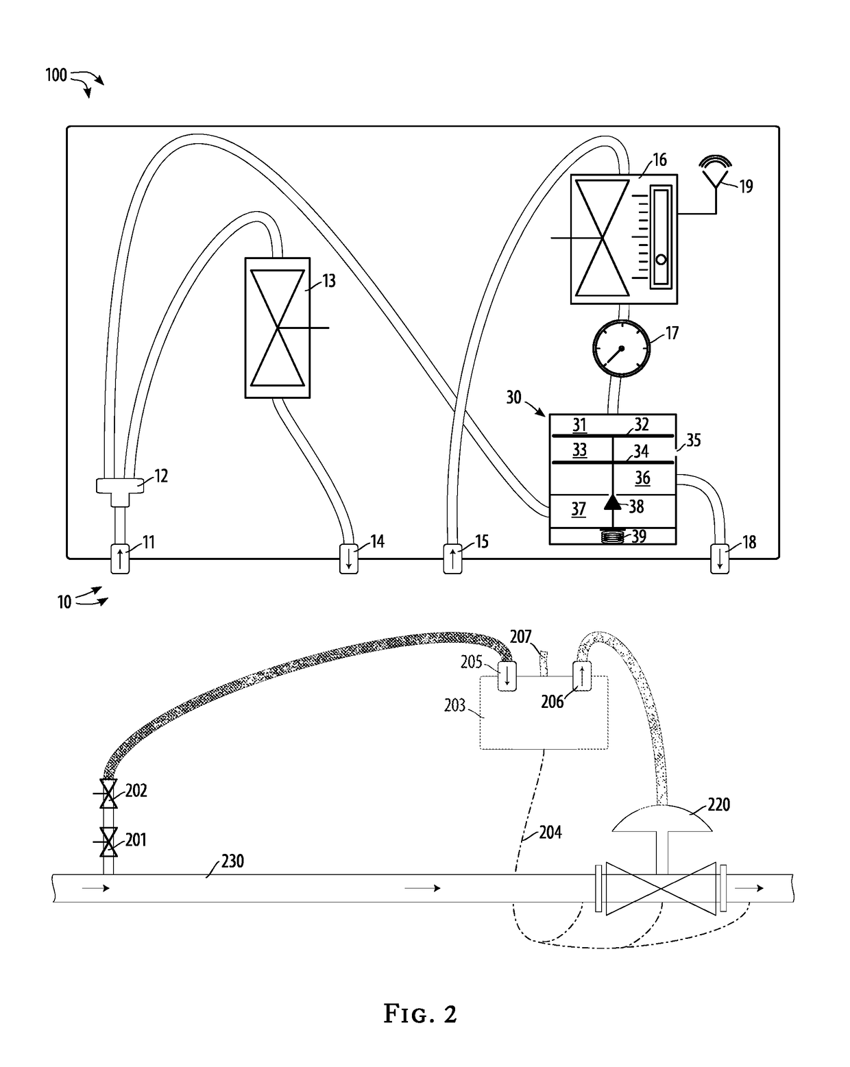
[0027]Referring to FIG. 2, illustrating the standard operation of pipeline control with this invention not engaged, from the high pressure of gas in the pipeline 230, which would typically be about 600 p.s.i., a standard control-level pressure of gas, typically 15 p.s.i., is produced by passage through a high-to-medium regulator 201 and a medium-to-standard regulator 202. The gas at standard control-level pressure is s...


PUM


Abstract

A pipeline-waste-gas reduction method to reduce the amount of gas wasted by existing high-pressure pipelines having existing pipeline controllers and existing actuator-based control valves, by reducing the pressure of gas sent to existing pipeline controllers by a determined factor, consequently reducing the amount of gas wasted by the controllers, and then increasing control pressure returned by the controllers by the same factor, ensuring that the proper control pressure is sent to the existing actuator-based control valves.

Description

BACKGROUND OF THE INVENTION[0001]This invention provides a pipeline-waste-gas reduction method to reduce the amount of gas wasted by existing high-pressure pipelines having existing pipeline controllers and existing actuator-based control valves.[0002]High-pressure gas pipelines, which can be thought of as “natural gas” pipelines, must be regulated by control valves to allow, prevent, or partially allow flow of high-pressure gas in a given segment of the pipeline. Such regulation is achieved by existing equipment, specifically existing controllers which use a reduced, control-level pressure of the gas in the pipeline as a means of signaling whether a control valve should be closed or partially closed, and existing control valves which employ actuators driven by that same reduced, control-level pressure of the gas in the pipeline. The remote locations of many of the control valves, and the dangers of explosion or failure, influenced the development of the existing system, which uses ...

Claims


Application Information

Patent Timeline
Patent Type & Authority Applications(United States)
IPC IPC(8): F17D5/02
CPCF17D5/02G05D16/2086G05D16/2093Y10T137/777F17D1/04F17D3/01F16K31/126G05D16/2095F16K31/00
Inventor DEVILLE, CHADDEVILLE, WAYNE
Owner DEVILLE CHAD
Why Eureka
Try Eureka