Supercharge Your Innovation With Domain-Expert AI Agents!

Angular velocity sensor correction device and method for correcting output signal from angular velocity sensor, and direction estimation device and method for estimating direction by correcting output signal from angular velocity sensor

Active Publication Date: 2017-05-11
JVC KENWOOD CORP A CORP OF JAPAN
View PDF6 Cites 4 Cited by
  • Summary
  • Abstract
  • Description
  • Claims
  • Application Information

AI Technical Summary

Benefits of technology

The present invention relates to an angular velocity sensor correction device and method that can accurately estimate the direction of an object based on positioning data and angular velocity data obtained from a GPS satellite. The device and method use a sensitivity coefficient derived from the positioning data and angular velocity data to correct the angular velocity output from the sensor. The device and method also use a correlation coefficient derived from the positioning data and angular velocity data to determine the effectiveness of the positioning data in estimating the direction. The technical effects of the invention include improved accuracy in estimating the direction of an object and improved efficiency in updating the direction based on changes in positioning data.

Problems solved by technology

Conventionally, the offset value of an angular velocity sensor has been corrected by using an output voltage from the angular velocity sensor, occurring when a vehicle is stopped or traveling straight, i.e., when angular velocity is “0.” However, in the case where a vehicle is not stopped frequently, i.e., when a vehicle is traveling on an expressway, or when it is traveling in an area with little traffic for a long time, it becomes difficult to regularly correct the offset value of an angular velocity sensor, whereby the accuracy of the offset value is likely to be decreased.
Because even the correction of the offset value occurring when a vehicle is traveling straight, in which the output voltage from an angular velocity sensor tends to become accurately “0”, is likely to be dependent on the shape of a road or a driving situation of a driver, it is difficult to regularly perform the correction.

Method used


Image

  • Angular velocity sensor correction device and method for correcting output signal from angular velocity sensor, and direction estimation device and method for estimating direction by correcting output signal from angular velocity sensor
  • Angular velocity sensor correction device and method for correcting output signal from angular velocity sensor, and direction estimation device and method for estimating direction by correcting output signal from angular velocity sensor
  • Angular velocity sensor correction device and method for correcting output signal from angular velocity sensor, and direction estimation device and method for estimating direction by correcting output signal from angular velocity sensor

Examples


embodiment 1

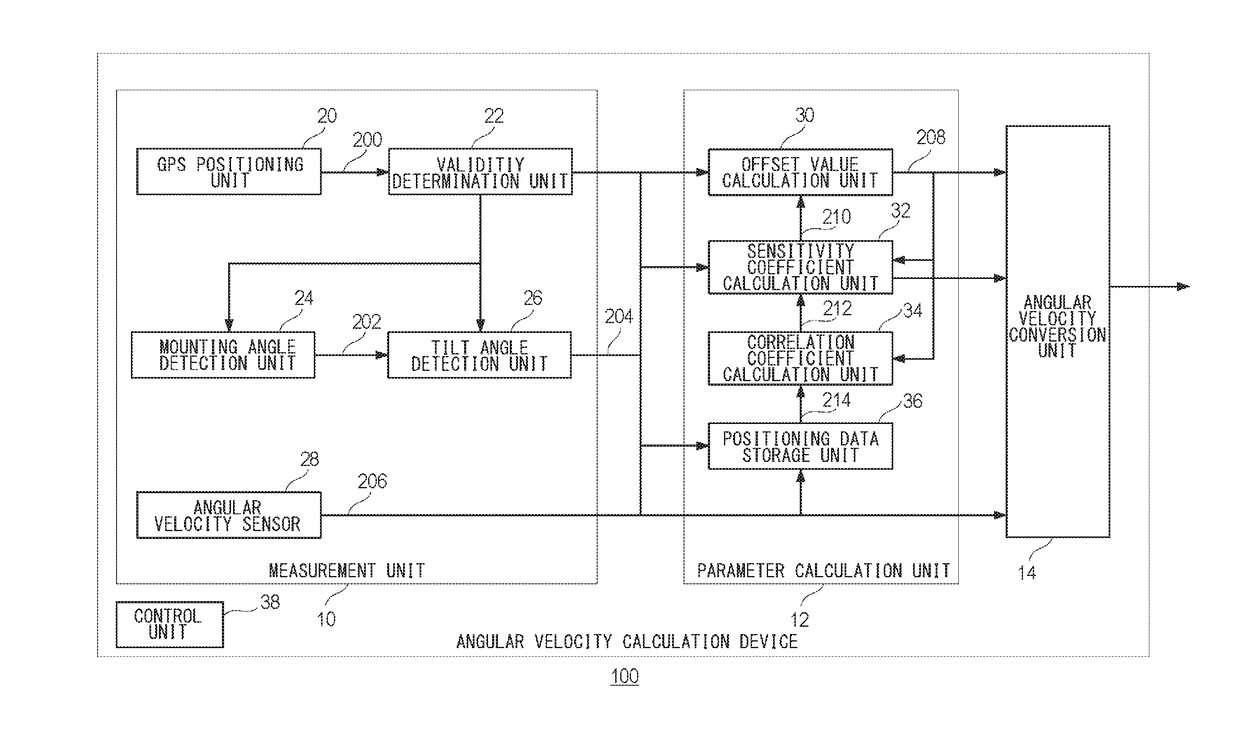
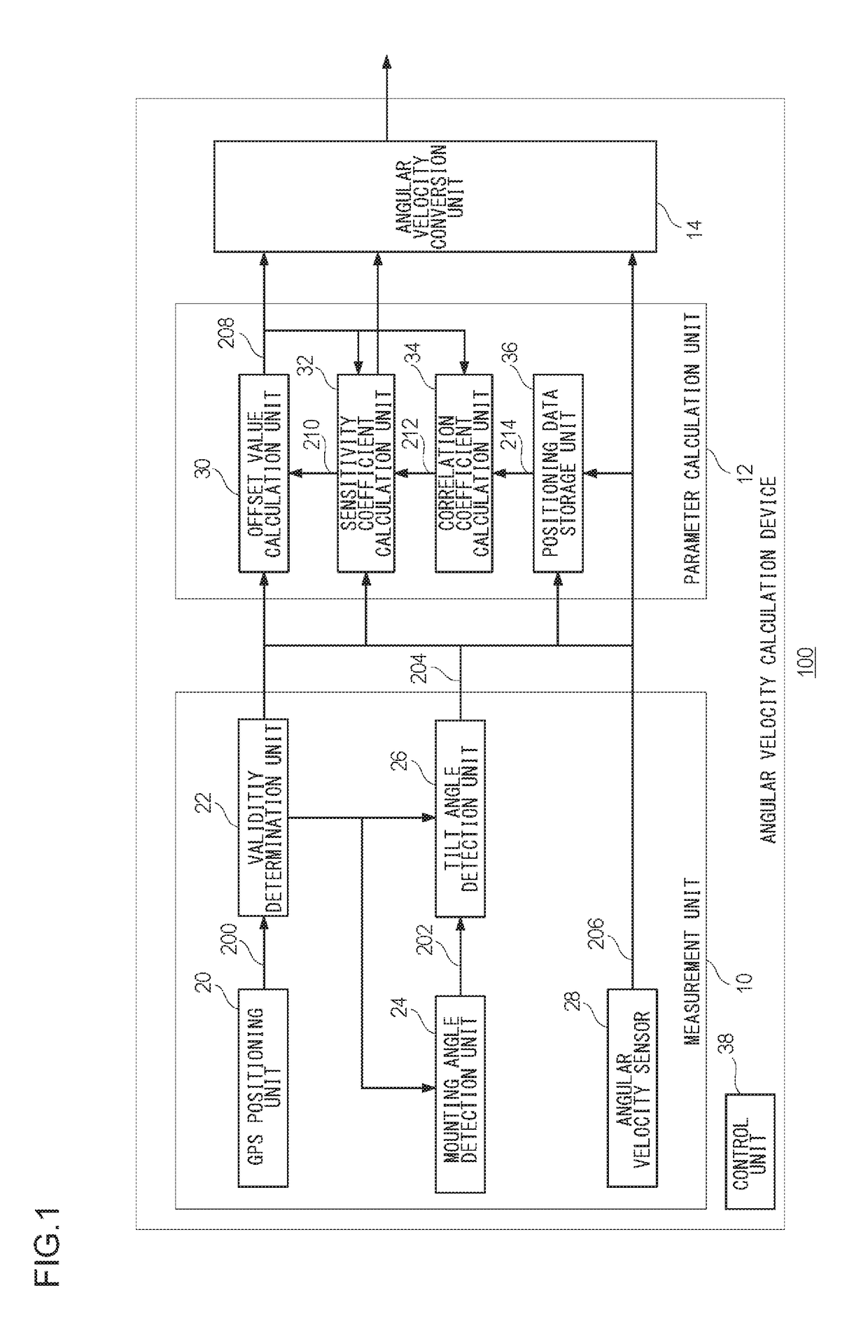
[0035]Prior to the specific description of the present invention, the outline thereof will be given first. The present embodiment relates to an angular velocity calculation device that is installed in a vehicle, etc., for deriving angular velocity occurring when the vehicle is turning. The angular velocity calculation device derives angular velocity by using an offset value and a sensitivity coefficient for an output voltage from an angular velocity sensor. In Equation (3) for deriving the sensitivity coefficient of an angular velocity sensor, Voffset is not stabilized by an influence of a change in temperature, etc., and hence when the number of samples is increased, an error in the sensitivity coefficient may be increased. Also, in Equation (3) for deriving the sensitivity coefficient of an angular velocity sensor, when an amount of change in direction Δθ is determined from the GPS direction acquired from a GPS satellite, the accuracy of the GPS direction may be decreased dependin...

embodiment 2

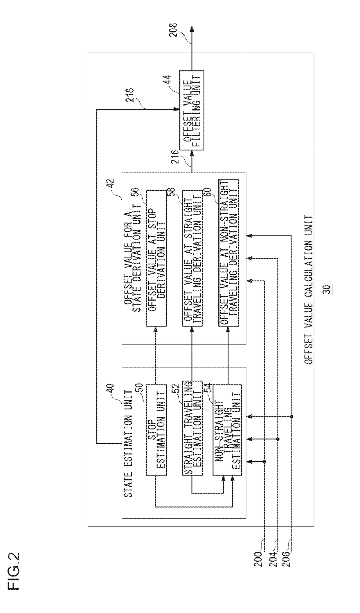
[0075]Embodiment 2 will now be described. Similarly to Embodiment 1, Embodiment 2 also relates to an angular velocity calculation device in which angular velocity is derived by using an offset value and a sensitivity coefficient for an output voltage from an angular velocity sensor. In Equation (2) for deriving the offset value of an angular velocity sensor, when an amount of change in direction Δθ is determined from the GPS direction acquired from a GPS satellite, the accuracy of the GPS direction may be decreased depending on the state of receiving radio waves from the GPS satellite, whereby an error included in the offset value becomes large.

[0076]Also in Equation (2), when the amount of change in direction Δθ is determined from map data, the direction of a road based on the map data does not always and completely match the direction of travel of a vehicle, whereby an error included in the offset value may become large. Further, in Equation (2) for deriving the offset value of an...

embodiment 3

[0088]Embodiment 3 will now be described. Embodiment 3 relates to a direction estimation device that estimates a direction by using angular velocity derived in the angular velocity calculation device described above. Even if the offset of an angular velocity sensor and a sensitivity coefficient are corrected, small errors are accumulated, and an error included in a position by self-contained navigation may become remarkable. Accordingly, when a vehicle is traveling in an area where a state of receiving GPS is bad, a combination ratio in self-contained navigation becomes large over a long period of time, and hence an error may be included in the estimated position.

[0089]In this case, when the state of receiving GPS becomes good, it is necessary that the combination ratio of the position calculated from GPS is increased such that an error included in the estimated position is corrected in a short period of time. Accordingly, in a direction estimation device according to the present em...


PUM


Abstract

A GPS positioning unit acquires GPS positioning data of an object positioned based on a signal from a GPS satellite, and an angular velocity sensor acquires an output signal of the object. A sensitivity coefficient calculation unit sequentially derives a temporary sensitivity coefficient of the angular velocity sensor based on the GPS positioning data and the output signal. The sensitivity coefficient calculation unit derives a sensitivity coefficient for correcting the angular velocity output from the angular velocity sensor, by performing statistical processing on the temporary sensitivity coefficient of the angular velocity sensor that has been sequentially derived. A correlation coefficient calculation unit derives a correlation coefficient based on the GPS positioning data and the output signal. The sensitivity coefficient calculation unit changes a forgetting coefficient to be used when the statistical processing is performed, in accordance with the correlation coefficient.

Description

CROSS-REFERENCE TO RELATED APPLICATION[0001]This application is based upon and claims the benefit of priority from the Japanese Patent Application No. 2014-254267, filed on Dec. 16, 2014, Japanese Patent Application No. 2014-254268, filed on Dec. 16, 2014 and Japanese Patent Application No. 2014-254269, filed on Dec. 16, 2014, the entire contents of which are incorporated herein by reference.BACKGROUND[0002]1. Field[0003]The present invention relates to an angular velocity sensor correction technique and a direction estimation technique, and in particular, to a device and method for correcting an angular velocity sensor that correct an output signal from an angular velocity sensor and to a device and method for estimating a direction that estimate a direction by correcting an output signal from an angular velocity sensor.[0004]2. Description of the Related Art[0005]In automobile navigation systems, an optimal position is generally estimated by combining a position calculated from se...

Claims


Application Information

Patent Timeline
IPC IPC(8): G01C21/28G01S19/47G01C19/00
CPCG01C21/28G01S19/47G01C19/00G01C21/165G01C25/005G01S19/39G01S19/396
Inventor KONDOH, TAKAHIROSUGIYAMA, SEIICHIFUKUSHIMA, HIDENORI
Owner JVC KENWOOD CORP A CORP OF JAPAN
Features
  • R&D
  • Intellectual Property
  • Life Sciences
  • Materials
  • Tech Scout
  • Unparalleled Data Quality
  • Higher Quality Content
  • 60% Fewer Hallucinations
Learn More