
Angular velocity sensor correcting apparatus for deriving value for correcting output signal from angular velocity sensor, angular velocity calculating apparatus, angular velocity sensor correcting method, and angular velocity calculating method

a technology output signal, which is applied in the direction of speed/acceleration measurement, instruments, navigation instruments, etc., can solve the problems of deteriorating precision of offset value, difficult periodic correction of offset value, and difficulty in periodically correcting offset value of angular velocity sensor. achieve the effect of improving the accuracy of deriving angular velocity and short tim

Active Publication Date: 2010-04-29
JVC KENWOOD CORP A CORP OF JAPAN
View PDF1 Cites 40 Cited by
  • Summary
  • Abstract
  • Description
  • Claims
  • Application Information

AI Technical Summary

Benefits of technology

[0011]The present invention has been achieved in view of such situations and a general purpose of the invention is to provide a technique of improving precision of deriving angular velocity even in short time since startup.
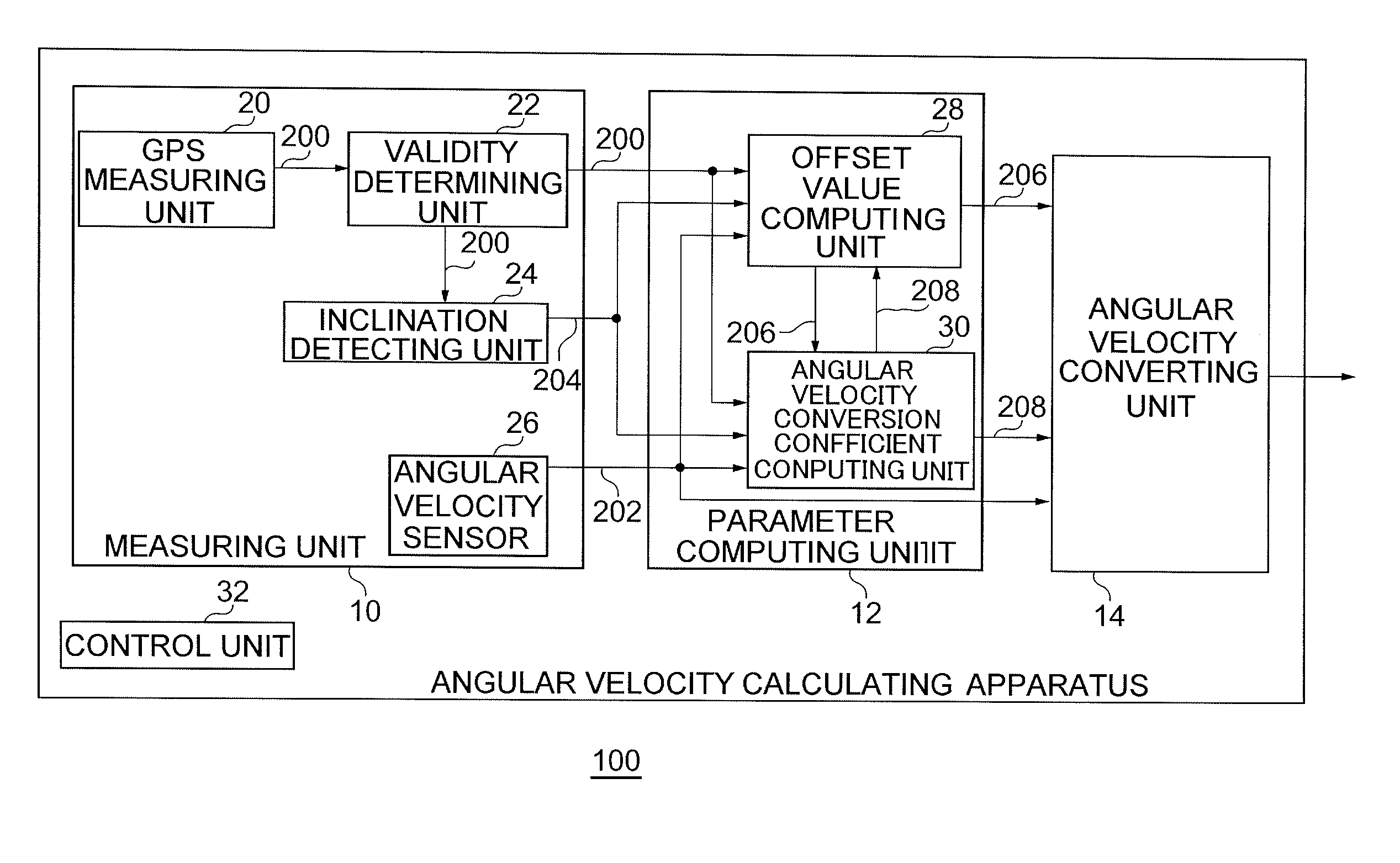
[0017]In the aspect, the offset value is derived by performing the statistical process on the temporary offset value while using the forgetting factor according to the running condition, and the angular velocity conversion coefficient is derived by performing the statistical process on the temporary angular velocity conversion coefficient while using the forgetting factor according to reliability. Thus, even in short time after startup, the precision of deriving the angular velocity can be improved.

Problems solved by technology

However, in the case where the frequency of stop of the vehicle is low such as running on an expressway or long-time running in an area where a traffic amount is small, it is difficult to periodically correct the offset value of the angular velocity sensor.
The precision of the offset value tends to deteriorate.
Correction of an offset value at the time of straight running when an output voltage from an angular velocity sensor accurately is “0” is easily influenced by the shape of a road and the driving state of the driver, so that it is difficult to periodically perform the correction.
Under such situations, when the number of samples is increased since Voffset in the equation (3) is not stable until the stable state is obtained in which the change amount of the offset value is small with respect to the angular velocity conversion coefficient of the angular velocity sensor, there is the possibility that an error in the angular velocity conversion coefficient increases.
Consequently, for example, in running of about 30 minutes or less, it is very difficult to accurately correct the angular velocity conversion coefficient of the angular velocity sensor, and precision of deriving the angular velocity is not high.
In the equation (3) for deriving the angular velocity conversion coefficient of the angular velocity sensor, in the case where the orientation change amount Δθ is obtained from the GPS orientation obtained from the GPS satellite, the precision of the GPS orientation deteriorates depending on the reception state of radio waves from the GPS satellite, so that an error included in the angular velocity conversion coefficient increases.
In the case where the orientation change amount Δθ is obtained on the basis of the map data in the equation (3), the road orientation based on the map data and the vehicle running orientation do not always match perfectly, so that an error included in the angular velocity conversion coefficient increases.

Method used


Image

  • Angular velocity sensor correcting apparatus for deriving value for correcting output signal from angular velocity sensor, angular velocity calculating apparatus, angular velocity sensor correcting method, and angular velocity calculating method
  • Angular velocity sensor correcting apparatus for deriving value for correcting output signal from angular velocity sensor, angular velocity calculating apparatus, angular velocity sensor correcting method, and angular velocity calculating method
  • Angular velocity sensor correcting apparatus for deriving value for correcting output signal from angular velocity sensor, angular velocity calculating apparatus, angular velocity sensor correcting method, and angular velocity calculating method

Examples


first embodiment

[0038]Prior to concrete description of the present invention, outline will be described first. An embodiment of the present invention relates to an angular velocity calculating apparatus mounted on a vehicle or the like and for deriving angular velocity accompanying turn of a vehicle. The angular velocity calculating apparatus derives angular velocity using an offset value and an angular velocity conversion coefficient for an output voltage from an angular velocity sensor. As described above, for a predetermined period since startup, the angular velocity sensor is influenced by fluctuations in temperature, so that an offset value is not accurately derived. An error in the offset value exerts an influence on calculation precision of the angular velocity conversion coefficient. As a result, in such a state, precision of angular velocity deteriorates. To address the problem, the angular velocity calculating apparatus of the embodiment executes the following process.

[0039]The angular ve...

second embodiment

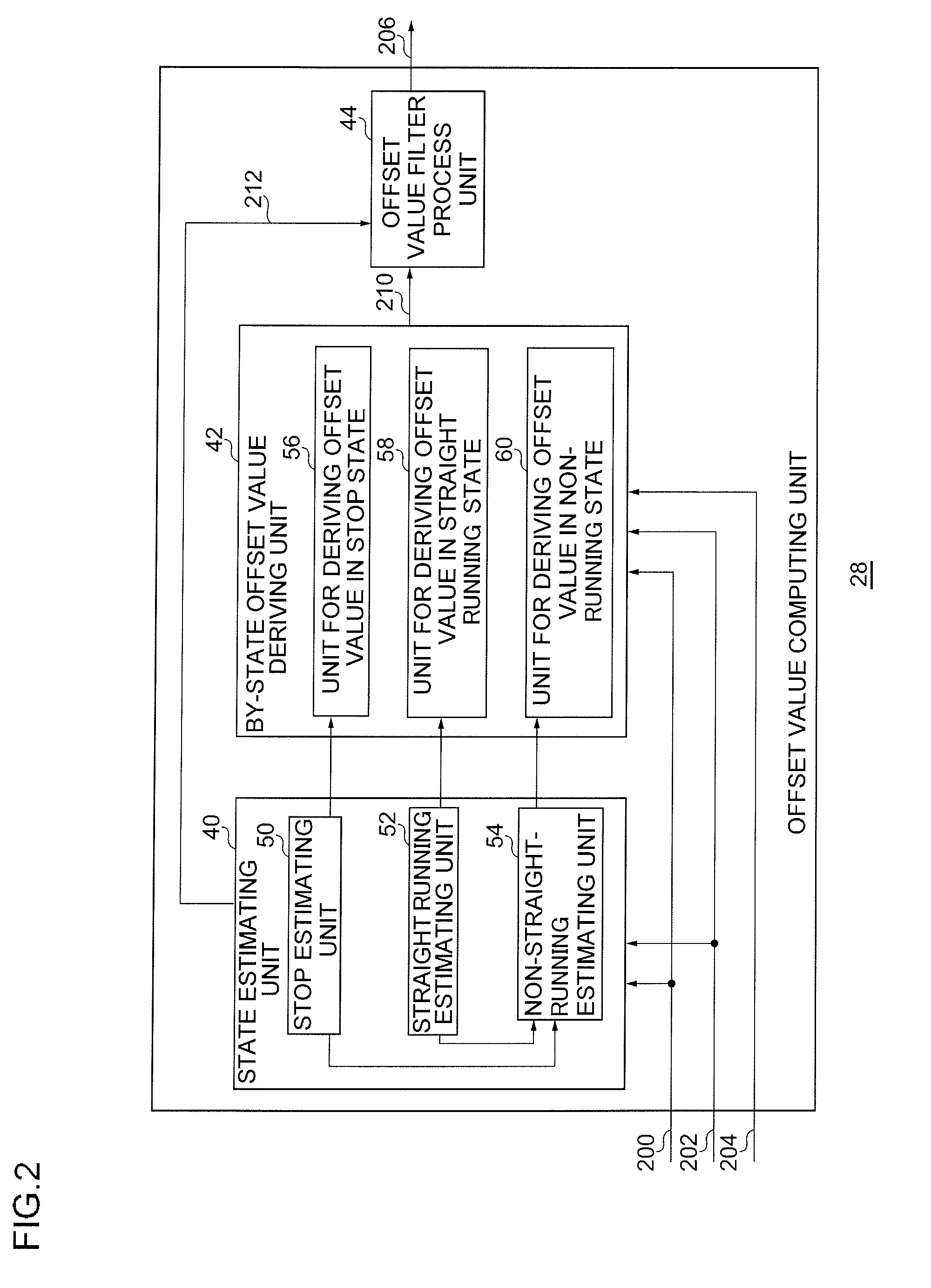
[0082]A second embodiment relates to the angular velocity calculating apparatus 100 like the first embodiment. In the first embodiment, the running conditions are classified into the stop state, the straight running condition, and the non-straight-running condition. The by-state offset value deriving unit 42 and the offset value filter process unit 44 execute similar processes on the stop state and the straight running condition. In the first embodiment, therefore, it can be said different processes are substantially performed on the two states. On the other hand, the angular velocity calculating apparatus 100 as the second embodiment sets different values as the forgetting factor for the stop state and the forgetting factor for the straight running condition. Consequently, it can be said that different processes are performed in the three states in the second embodiment. The angular velocity calculating apparatus 100, the offset value computing unit 28, the offset value filter proc...

third embodiment

[0085]A third embodiment relates to the angular velocity calculating apparatus 100 like the foregoing embodiments and, particularly, to the angular velocity conversion coefficient computing unit 30. Conventionally, according to the operation time of the angular velocity sensor 26, the forgetting factor in the angular velocity conversion coefficient filter unit 82 is changed. On the other hand, as described above, due to deterioration in the precision of the GPS orientation depending on the reception state of radio waves from a GPS satellite, an error included in the angular velocity conversion coefficient increases. In such a case as well, to suppress deterioration in the precision of the angular velocity conversion coefficient, the angular velocity conversion coefficient computing unit 30 of the third embodiment estimates reliability of a temporary angular velocity conversion coefficient, and sets a forgetting factor in the angular velocity conversion coefficient filter unit 82 acc...


PUM


Abstract

A measuring unit obtains measurement data of an object measured on the basis of a signal from a GPS satellite and angular velocity of an object output from an angular velocity sensor. An offset value computing unit estimates a running condition of the object on the basis of the measurement data and the angular velocity. The offset value computing unit sequentially derives temporary offset values while changing combination of the measurement data and the angular velocity in accordance with the estimated running condition of the object and, after that, executes statistical process on the temporary offset values, thereby deriving an offset value. An angular velocity conversion coefficient computing unit sequentially derives temporary angular velocity conversion coefficients on the basis of the measurement data and the angular velocity and, after that, executes statistical process on the temporary angular velocity conversion coefficients, thereby deriving an angular velocity conversion coefficient. An angular velocity converting unit derives final angular velocity on the basis of the angular velocity conversion coefficient, the offset value, and the angular velocity.

Description

CROSS-REFERENCE TO RELATED APPLICATIONS[0001]The present application claims the priority benefit of Japanese patent application number JP 2008-274871 filed Oct. 24, 2008, the disclosure of which is incorporated herein by reference.BACKGROUND OF THE INVENTION[0002]1. Field of the Invention[0003]The present invention relates to an angular velocity sensor correcting technique and an angular velocity calculating technique and, more particularly, to an angular velocity sensor correcting apparatus, an angular velocity calculating apparatus, an angular velocity sensor correcting method, and an angular velocity calculating method for deriving a value for correcting an output signal from an angular velocity sensor.[0004]2. Description of the Related Art[0005]In a navigation apparatus for a vehicle, generally, an optimum position is estimated by combining a position calculated by self-contained navigation and a position calculated from a Global Positioning System (GPS). In the self-contained ...

Claims


Application Information

Patent Timeline
Patent Type & Authority Applications(United States)
IPC IPC(8): G06F19/00G01S19/39G01P3/00G01C19/00G01C21/26G01C21/28G06F17/18
CPCG01C21/28
Inventor KONDOH, TAKAHIRO
Owner JVC KENWOOD CORP A CORP OF JAPAN
Learn More